

Underwater topography measurement boat as well as manufacturing method and measurement method
A technology for underwater topography and survey ships, which is applied in the field of survey ships, can solve the problems of increased survey costs, disadvantages, and high physical exertion of surveyors, and achieve the effect of improving accuracy
- Summary
- Abstract
- Description
- Claims
- Application Information
AI Technical Summary
Problems solved by technology
Method used
Image

Examples
Embodiment 1
[0158] Consists of at least one survey ship (30), reference station (29), main control equipment (37) and remote control equipment (44), the reference station (29), main control equipment (37) and remote control equipment (44) are Controlling is performed on the shore of the surveying water area (35), and multiple surveying ships (30) are simultaneously controlled by the reference station (29), the main control device (37) and the remote control device (44) according to actual needs.
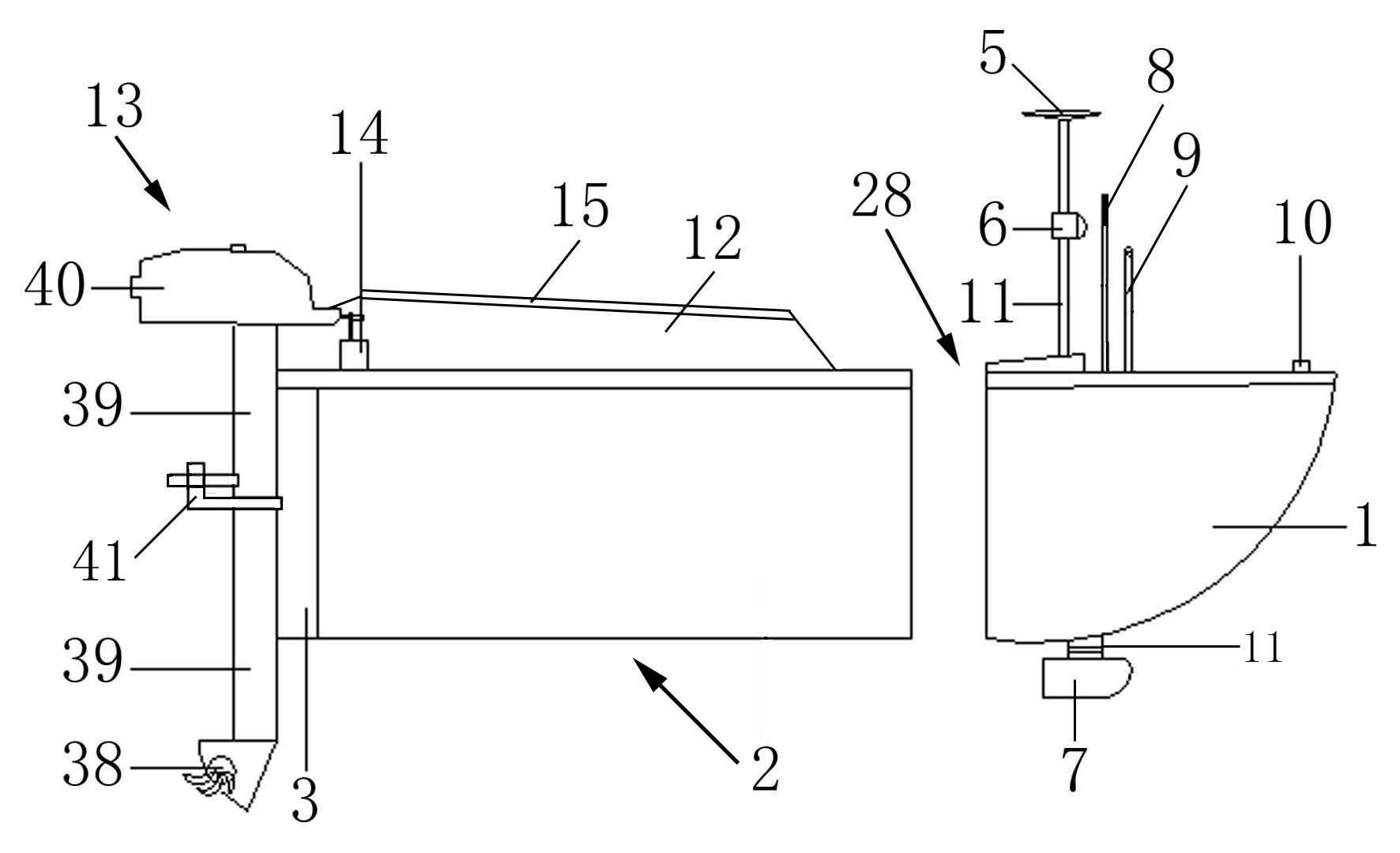
[0159] The measuring ship (30) is composed of a hull, a control system, a navigation course control system, a positioning system, a measuring system and a communication system, and the overall hull of the measuring ship (30) is composed of independent sections of the bow (1) and the hull (2) , the bow (1) is sealed as a whole, the upper part of the bow (1) is the ship deck, the front end of the bow (1) is a sharp point, the rear end of the bow (1) is flat as a whole, the rear end of the bow (1) i...
Embodiment 2
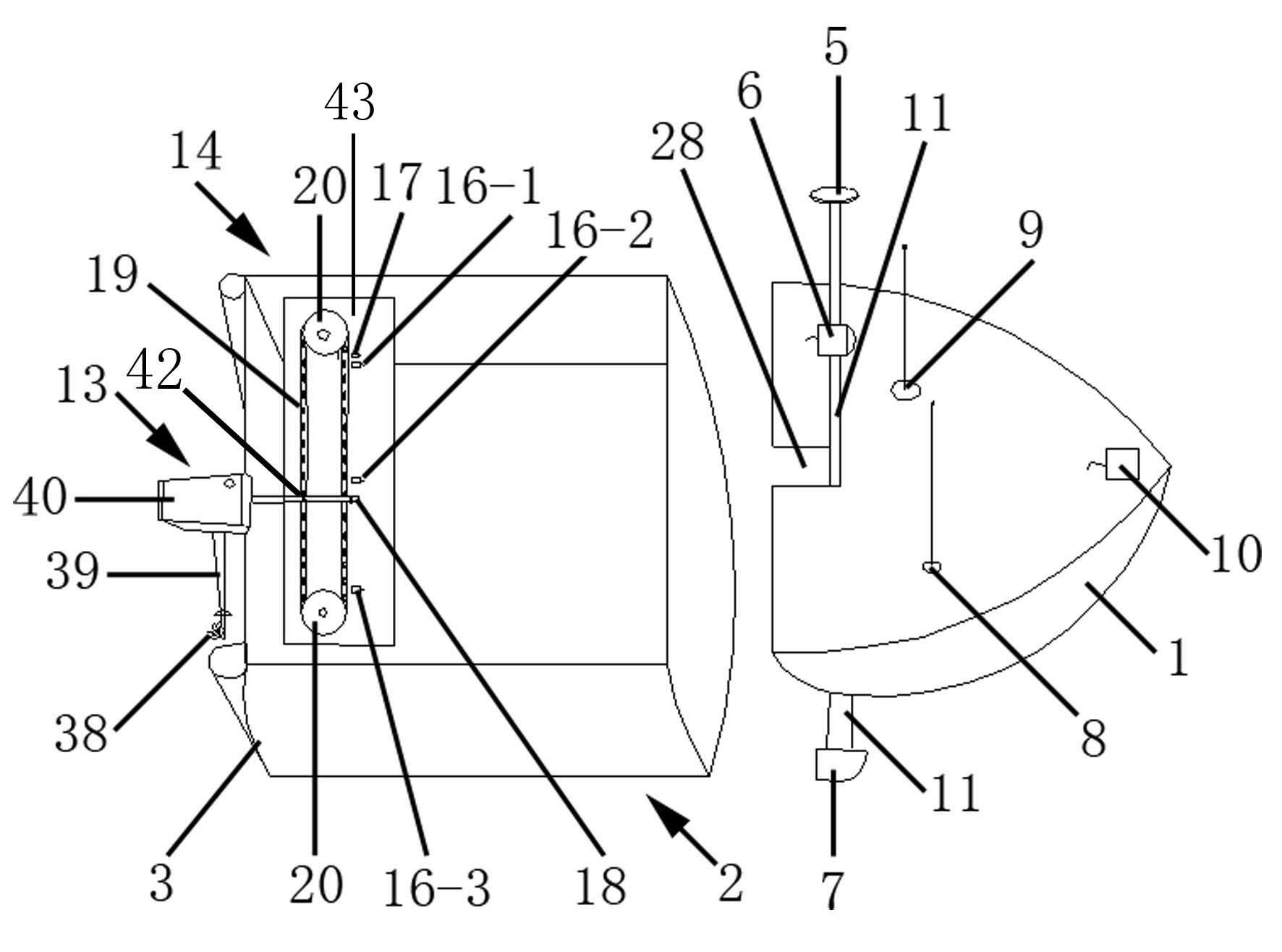
[0161] The equipment installation column (11) is columnar as a whole, and the middle part of the equipment installation column (11) is fixedly installed in the underwater detection hole (28). The equipment installation column (11) is columnar as a whole, and the equipment installation column (11) runs through the underwater detection hole (28), the lower end of the equipment installation column (11) passes through the lower end of the underwater detection hole (28), and the top end of the lower end of the equipment installation column (11) is fixedly provided with the depth sounder probe (7 ), the depth sounder probe (7) transmits signals underwater and receives the signal reflected by the measured water bottom (31), the depth sounder probe (7) is connected with the depth sounder (27) through a wire, and the depth sounder probe (7) Directly underwater detection of topography, topography and depth of the measured water bottom (31) along the measurement section line (36).
[016...
Embodiment 3
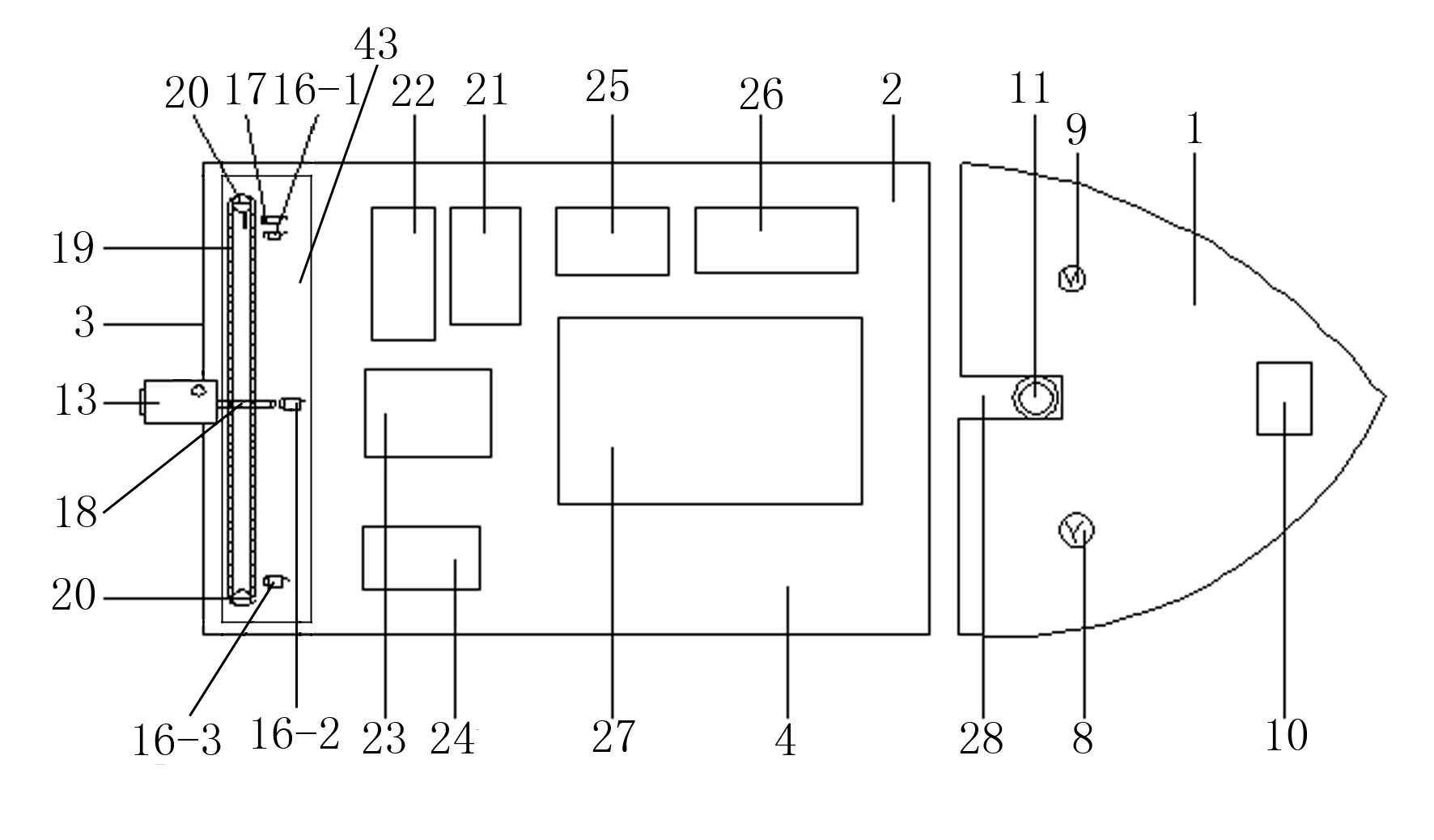
[0168] The hull (2) is in the shape of a load-bearing ship as a whole, and the load-carrying compartment (4) is arranged on the hull (2), and the stern (3) at the tail end of the hull (2) sets the driving mechanism of the navigation course control system by installing the clip (41) (13), the driving mechanism (13) drives the navigation of the measuring ship (30), the upper part of the hull (2) is installed with the hull hatch (12), and the hull hatch (12) coincides with the hull (2) , the hull hatch (12) shields and protects the equipment in the carrying compartment (4), the top of the hull hatch (12) installs a solar panel (15), and the solar panel (15) covers the hull hatch (12 ), the solar panel (15) is connected with the storage battery pack (24) through a line, and transmits power to the storage battery pack (24).
[0169] The data communication radio station (26), GPS radio station (25), depth sounder (27), GPS equipment (21), battery pack (24), power supply module (22) ...
PUM
 Abstract
Description
Claims
Application Information