Temperature measuring device based on high-pressure gas Rayleigh-Brillouin scattering spectrum

A Brillouin scattering and gas temperature technology, applied in the field of experimental devices, can solve problems such as unsatisfactory measurement results, and achieve the effects of improving reliability, stability, high resolution, and high sensitivity

Inactive Publication Date: 2012-07-18
NANCHANG HANGKONG UNIVERSITY
View PDF2 Cites 11 Cited by
  • Summary
  • Abstract
  • Description
  • Claims
  • Application Information

AI Technical Summary

Problems solved by technology

When measuring with the contact temperature measurement method, due to the disturbance of the temperature sensing element to the temperature field, the thermal inertia of the sensor and the limitation of the temperature measurement area, the measurement results are not ideal

Method used


Image

  • Temperature measuring device based on high-pressure gas Rayleigh-Brillouin scattering spectrum
  • Temperature measuring device based on high-pressure gas Rayleigh-Brillouin scattering spectrum
  • Temperature measuring device based on high-pressure gas Rayleigh-Brillouin scattering spectrum

Examples


Embodiment 1

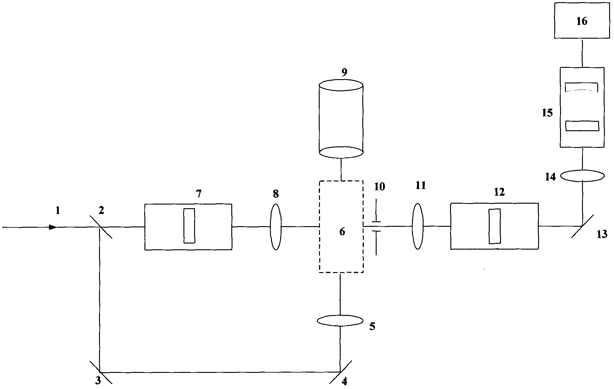
[0021] as attached figure 1 As shown, the device includes: injection pulse laser or continuous laser (1), 355nm total mirrors (2, 3, 4, 13), filter system (7), collimation and filter system (12), Slits (10, 18, 21, 23), convex lenses (5, 8, 11, 14, 17, 19, 20, 22), scattering cells (6), scanning interferometers (15), energy recovery cells (9) , Signal detection device (16).

[0022] The laser (1) outputs vertically polarized narrow-band light with a wavelength of 355nm, 95% of the light is reflected to the total reflection mirror (3) through the 355nm total reflection mirror (2), and 5% of the light is transmitted to the filter system (7) , after passing through the convex lens (8), it enters into the scattering pool (6) for correction of the optical path. The light passing through the total reflection mirror (3) passes through the total reflection mirror (4) and the focusing lens (5), and enters the scattering cell (6), interacts with gas molecules to generate a scattering ...

Embodiment 2

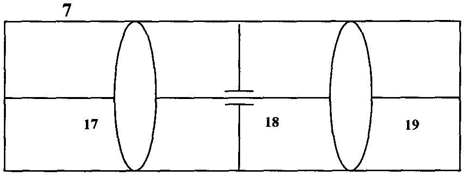
[0024] as attached figure 2 Shown, filter system (7) comprises: convex lens (17,19) and slit (18)

[0025] In order to calibrate the experimental device in the experiment, 5% of the light is set as reference light, and in order to ensure the quality of the laser beam, 5% of the laser light passes through the convex lens 17 (f 17 =10cm), slit 18(D 18 =50um), convex lens 19 (f 19 =10cm) to filter the spatial filtering system, the purpose is to eliminate the spatial fluctuation of the beam and make the field intensity distribution on the section uniform.

Embodiment 3

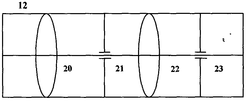
[0027] as attached image 3 As shown, the light filtering and light spot diameter integration system (12) includes: convex lenses (20, 22) and slits (21, 23).

[0028] In order to detect the weak scattering signal in the experiment and realize the detection of the Brillouin scattering signal, the scattering signal must be coupled into the high-resolution spectroscopic system (15) as much as possible, so the slit 10, Lens 11 (D 10 = 0.1 mm, f 11 =75mm) and filter and light spot diameter integration system (12), the signal first passes through the slit 10 (D 10 =0.1mm) reduces the spatial divergence angle, is collimated by the lens 11 (f=75mm), and then is collimated by the lens 20 (f 20 =50mm) focus to the slit 21 (D 21 =50um) to carry out spatial filtering, finally by the lens 22 (f 22 =50mm) collimated again, in order to limit the diameter of the spot within the acceptable range of the scanning interferometer, pass it through the slit 23 (D 23 =1.5mm) to correct the spo...


PUM


Abstract

The invention relates to a temperature measuring device based on high-pressure gas Rayleigh-Brillouin scattering spectrum. The device can probe the Brillouin frequency shifting rate in the Rayleigh-Brillouin scattering spectrum at different pressures to measure acoustic velocity at different pressures so as to achieve temperature retrieval. 355nm single-die laser enters the high pressure gas to mutually interact with various gas molecules in the gas; the scattering signal passes through an F-P scanning interferometer and is received by a photon detector, therefore, the Rayleigh-Brillouin scattering spectrum of the high pressure gas can be obtained. According to the temperature measuring device, the precise measurement on the gas temperature at different pressures is achieved through analysis and calculation of the spectral function.

Description

Technical field: [0001] The invention relates to an experimental device for reversing gas temperature under different pressures based on high-pressure gas Rayleigh-Brillouin scattering spectrum. Background technique: [0002] In industrial production, temperature sensors such as thermocouples, thermal resistances, and liquid-in-glass thermometers are widely used to measure temperature. When measuring high-temperature and high-pressure airflow, the sensor faces complex heat transfer effects when the sensor is in thermal equilibrium at the measurement end. Therefore, during the measurement, the temperature of the temperature sensor is not equal to the actual temperature of the airflow. The measurement of the instantaneous temperature of high-temperature gas is even more difficult in temperature measurement, the main reason is that the temperature is high, the pressure is strong, and the temperature changes quickly. [0003] At present, the commonly used methods for measuring...

Claims


Application Information

Patent Timeline
Patent Type & Authority Applications(China)
IPC IPC(8): G01J5/10G01J3/28
Inventor 何兴道张晓吴涛丁文超江榕宏
Owner NANCHANG HANGKONG UNIVERSITY
Why Eureka
Try Eureka