Method for operating a D.C. generator

A technology of DC motor and DC power supply, which is applied to the starter of a single DC motor, the deceleration device of an AC motor, and the motor start of an engine, etc. It can solve the problems of reduced efficiency, over-thick coating, damage, etc., and can improve the service life , easy-to-obtain effect

Inactive Publication Date: 2012-07-18
SEG AUTOMOTIVE GERMANY GMBH
View PDF5 Cites 6 Cited by
  • Summary
  • Abstract
  • Description
  • Claims
  • Application Information

AI Technical Summary

Problems solved by technology

Too little detergent content improves the sliding behavior of the brushes on the commutator, but after a long operating time the coating becomes too thick and the transition resistance of the brushes to the commutator becomes too high, This leads to a reduction in efficiency and also damages the commutation system due to the increased temperature caused by the greater transition resistance, and current build-up in the transition region adversely affects the service life of the motor

Method used


Image

  • Method for operating a D.C. generator
  • Method for operating a D.C. generator
  • Method for operating a D.C. generator

Examples


Embodiment Construction

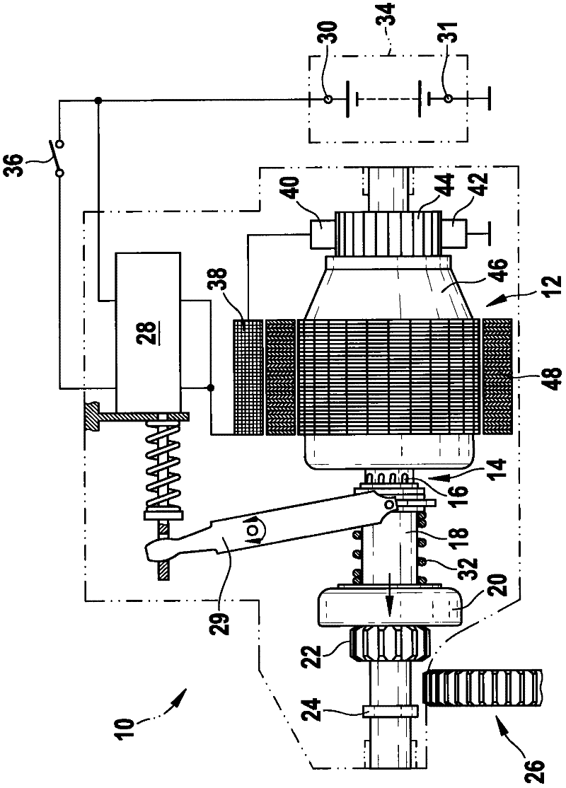
[0016] figure 1 The mechanical structure of a DC electric machine embodied as a displacement-screw starter for an internal combustion engine is schematically shown. The starter 10 has a starter motor 12 , the driven shaft 14 of which has a multi-start thread 16 which interacts with a corresponding nut thread in a drive rod 18 . Alternatively, the driven shaft 14 is driven via an interposed planetary gear, not shown. The driving rod 18 is fixedly connected with the outer ring of the free rolling ring 20 , the inner ring of which supports the pinion 22 . The pinion 22 and the free-running ring 20 are mounted on the output shaft 14 so as to be axially displaceable up to a stop 24 . The pinion 22 meshes here with a ring gear 26 of the internal combustion engine, not shown. by means of Figure 5 with 6 Axial movement is effected by a relay device 28 shown in detail in , which is engaged on the free-running ring 20 via a deflection rod 29 and an engaging spring 32 . A battery ...


PUM


Abstract

The invention relates to a method for operating a d.c. generator, especially a starter (10) for an internal combustion engine, the armature (46) of the machine being fed by brushes (42) and a commutator (44) from a constant voltage source (30, 31). The patination of the commutation system is monitored by the machine-specific startup current (I) and corrected by changing the operating parameters of the machine. The monitoring of the startup current (I) of the machine is carried out preferably on the basis of the power fade [delta]U during the startup in the main current circuit of the machine.

Description

technical field [0001] The invention relates to a method for the operation of a direct current motor as described in the preambles of the independent claims. Background technique [0002] Methods are known in which, in particular, special attention must be paid to the composition and construction of the brushes in order to achieve favorable conditions with regard to the service life of the commutation system and the commutation process. For this purpose, for example, an electric composite brush is disclosed in DE 60 2004 006 086 T2, which discloses two layers with different electrical resistances and different material compositions for the stabilization of the tribological properties, thereby avoiding the use of separate Lubricate brushes. However, such composite brushes are only optimal for certain operating conditions of a certain electric machine. [0003] Particularly high demands are placed on the operating method of DC motors in the construction of starters for inter...

Claims


Application Information

Patent Timeline
Patent Type & Authority Applications(China)
IPC IPC(8): H02P9/30H02J7/14H02P1/18H02P1/16H01R43/14F02N11/08
CPCF02N2300/106H02K23/66F02N11/108F02N15/022F02N11/087H02K23/68H02P1/166F02N15/067H02P1/18
Inventor M·拜尔R·希宁
Owner SEG AUTOMOTIVE GERMANY GMBH
Why Eureka
Try Eureka