High-efficiency low-cost purification process of flue gas

A purification process and flue gas technology, used in chemical instruments and methods, dispersed particle separation, separation methods, etc., can solve problems such as unsatisfactory treatment efficiency, unintegrated treatment processes, and difficult removal of toxic organics, and achieves easy treatment and Effects of detoxification, reduction of processing load and equipment size, and processing cost savings

Inactive Publication Date: 2012-07-25
NANJING UNIV
View PDF5 Cites 8 Cited by
  • Summary
  • Abstract
  • Description
  • Claims
  • Application Information

AI Technical Summary

Problems solved by technology

However, on an international scale, the current method for dealing with industrial flue gas has serious defects in the following two aspects: one is that the process of the treatment process is complex, the equipment investment is large, the consumption of medicines is large, and the treatment cost is high (according to the report of the U.S. Environmental Agency, using the existing Methods, such as SCR, SNCR, SNCR-SCR and other single treatment of NOx, the average operating cost is as high as 1500-10000USD / t NOx); second, the treatment process cannot be integrated, that is, desulfurization, denitrification, dust removal, and removal of organic pollutants For example, dioxins cannot be matched with each other, and each works independently, or even after integration, the treatment efficiency of each section is not ideal, the desulfurization efficiency is only 90% or even lower, the denitrification efficiency is generally lower than 85%, and the dust removal efficiency is more difficult to control. Toxic organics are generally difficult to remove

Method used


Image

  • High-efficiency low-cost purification process of flue gas

Examples


Embodiment 1

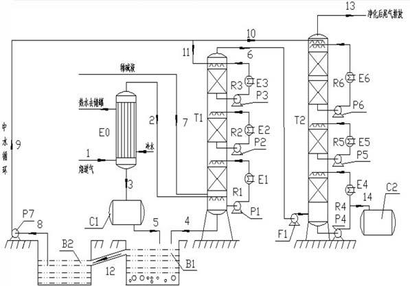
[0039] Now we are dealing with the flue gas of a company’s self-provided power plant. In terms of volume fraction, it contains CO 2 11.2%, O 2 8.49%, N 2 54%, H 2 O is 24%, SO 2 1509 mg / m 3 , NOx is 1212mg / m 3 , and the rest are other trace pollutants and soot. The flue gas flow rate is 1124980 m 3 / h, the flue gas temperature is 220°C. Using the above process, the flue gas enters the waste heat exchanger E0 through the pipeline 1, so that the temperature of the flue gas is reduced from 220°C to 115°C, and hot water is produced at the same time, and 350t / h liquid water with a temperature of 88°C can be obtained. Hot water storage tank for hot water users. Subsequently, the flue gas enters the lower part of the comprehensive washing tower T1 from the upper part of the waste heat exchanger E0 through the pipeline 2, and contacts with the first circulating liquid, the second circulating liquid and the third circulating liquid which flow countercurrently in stages, and sim...

Embodiment 2

[0046] Now we are dealing with the flue gas of domestic waste incineration with a processing capacity of 360t / d in a company. In terms of volume fraction, it contains CO 2 12.4%, O 2 7.63%, N 2 56.2%, H 2 O is 20.8%, SOx is 1434 mg / m 3 , NOx is 1056mg / m 3 , and the rest are other trace pollutants and soot. Flue gas flow rate is 45080 m 3 / h, the flue gas temperature is 120°C (has been cooled). Using the above process method, the flue gas enters the waste heat exchanger E0 through the pipeline 1, so that the temperature of the flue gas is reduced from 120°C to 85°C, and hot water is produced at the same time, and 8t / h liquid water with a temperature of 64°C can be obtained. Hot water storage tank for hot water users. Subsequently, the flue gas enters the lower part of the comprehensive scrubber T1 from the upper part of the waste heat exchanger E0 through the pipeline 2, and contacts with the first circulating liquid, the second circulating liquid and the third circulati...

Embodiment 3

[0053] Now we are dealing with the flue gas of domestic waste incineration with a processing capacity of 360t / d in a company. In terms of volume fraction, it contains CO 2 12.4%, O 2 7.63%, N 2 56.2%, H 2 O is 20.8%, SOx is 1434 mg / m 3 , NOx is 1056mg / m 3 , and the rest are other trace pollutants and soot. Flue gas flow rate is 45080 m 3 / h, the flue gas temperature is 120°C (has been cooled). Using the above process method, the flue gas enters the waste heat exchanger E0 through the pipeline 1, so that the temperature of the flue gas is reduced from 120°C to 85°C, and hot water is produced at the same time, and 8t / h liquid water with a temperature of 64°C can be obtained. Hot water storage tank for hot water users. Subsequently, the flue gas enters the lower part of the comprehensive scrubber T1 from the upper part of the waste heat exchanger E0 through the pipeline 2, and contacts with the first circulating liquid, the second circulating liquid and the third circulati...


PUM


Abstract

The invention provides a high-efficiency low-cost purification process of flue gas. The process comprises a heat exchange system, a comprehensive cleaning system, a denitration system and a waste liquid treatment system, wherein the comprehensive cleaning system is a comprehensive cleaning tower T1 consisting of 2 to 5 circular cleaning loops, the cleaning solution in the first circular cleaning loop is diluted alkaline solution, and the cleaning solutions in subsequent circular cleaning loops is water, the cleaning solution after cleaning is recycled after neutralization and biochemical treatment, and the sludge generated after treatment is cleaned and detoxified regularly; and the denitration system is a denitrition tower T2 consisting of 2 to 4 circular absorption loops, the circular absorption solution is water, and the absorption solution after NOX is absorbed is diluted nitric acid which can be directly sold or used. The contents of various toxic and harmful substances in the flue gas emitted from the top of the denitration tower T2 can be respectively controlled to be that SOx is less than or equal to 5mg/m<3>, NOx is less than or equal to 50mg/m<3>, HCl is less than or equal to 5mg/m<3>, HF is less than or equal to 1mg/<3>, HBr is less than or equal to 1mg/m<3>, solid particles are less than or equal to 3mg/m<3>, and dioxin (DOX) is less than of equal to 0.001TEQng/m<3>, which are far superior to the emission standard of related flue gas of America, European Union and China.

Description

technical field [0001] The invention relates to a flue gas purification process. [0002] Background technique [0003] In today's world, coal-fired boilers, waste incinerators, waste gasifiers, etc. contain a variety of toxic and harmful substances in the flue gas during their work, such as sulfide (SO 2 , SO 3 etc.), halides (HCl, HF, HBr, etc.), nitrogen oxides (NOx), CO2, soot particles, dioxins, etc., which are the main factors causing air pollution. Therefore, industrial flue gas must be treated before being discharged. However, on an international scale, the current method for dealing with industrial flue gas has serious defects in the following two aspects: one is that the process of the treatment process is complex, the equipment investment is large, the consumption of medicines is large, and the treatment cost is high (according to the report of the U.S. Environmental Agency, using the existing Methods, such as SCR, SNCR, SNCR-SCR and other single treatment of ...

Claims


Application Information

Patent Timeline
Patent Type & Authority Applications(China)
IPC IPC(8): B01D53/75
Inventor 张志炳陈金明熊永生周政王宝荣
Owner NANJING UNIV
Why Eureka
Try Eureka