Control device of variable valve exhaust tube

A technology of control device and exhaust pipe, applied in the direction of exhaust device, muffler device, engine control, etc., can solve the problems of limiting the maximum horsepower of the engine, carbon deposition of the engine, and high cost, and achieve the effect of increasing the length

Active Publication Date: 2014-05-07
冯子光
View PDF7 Cites 0 Cited by
  • Summary
  • Abstract
  • Description
  • Claims
  • Application Information

AI Technical Summary

Problems solved by technology

[0002] Due to the current energy shortage, general civilian vehicles will emphasize fuel economy, so engineers will use various means to increase the exhaust back pressure of the exhaust pipe, which can increase the low-speed torque of the engine and reduce the fuel consumption of the car, but in this way It will also limit the maximum horsepower of the engine, because the exhaust pressure will increase greatly when the engine outputs high horsepower, and there will be a large amount of exhaust gas left in the cylinder after the exhaust stroke, which will affect the intake efficiency of the next intake stroke. The airflow throughput of the engine becomes smaller, the rated maximum horsepower of the engine is severely reduced, and the acceleration response of the engine is relatively slow
Moreover, because the increase of exhaust pressure will also make the engine prone to knocking phenomenon at high power output, and the engine has serious carbon deposits, so some automobile manufacturers have introduced variable valve exhaust pipes, but they need to be controlled by computers, and it is difficult to do so. To stepless variable control, high cost and high maintenance cost

Method used


Image

  • Control device of variable valve exhaust tube
  • Control device of variable valve exhaust tube

Examples


Embodiment Construction

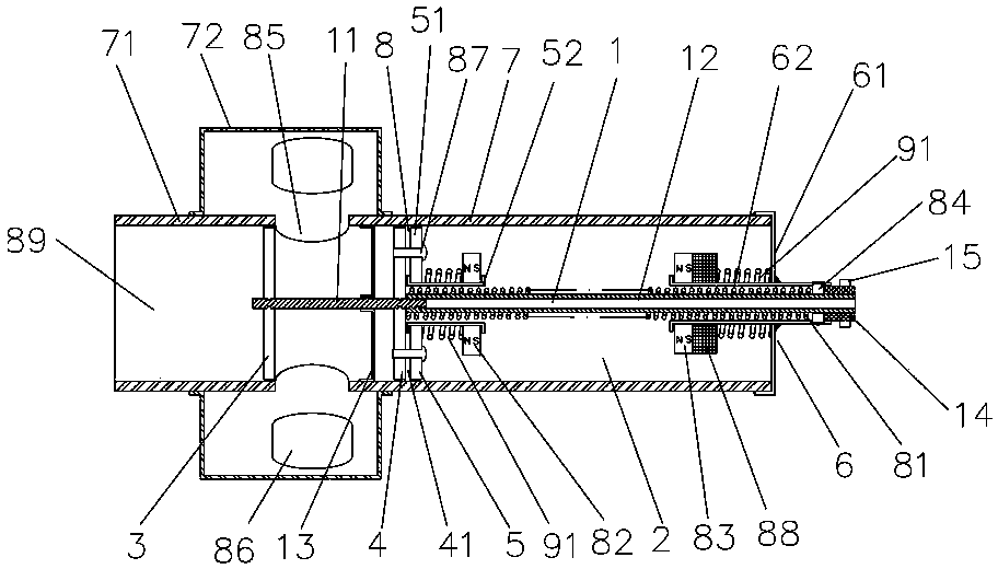
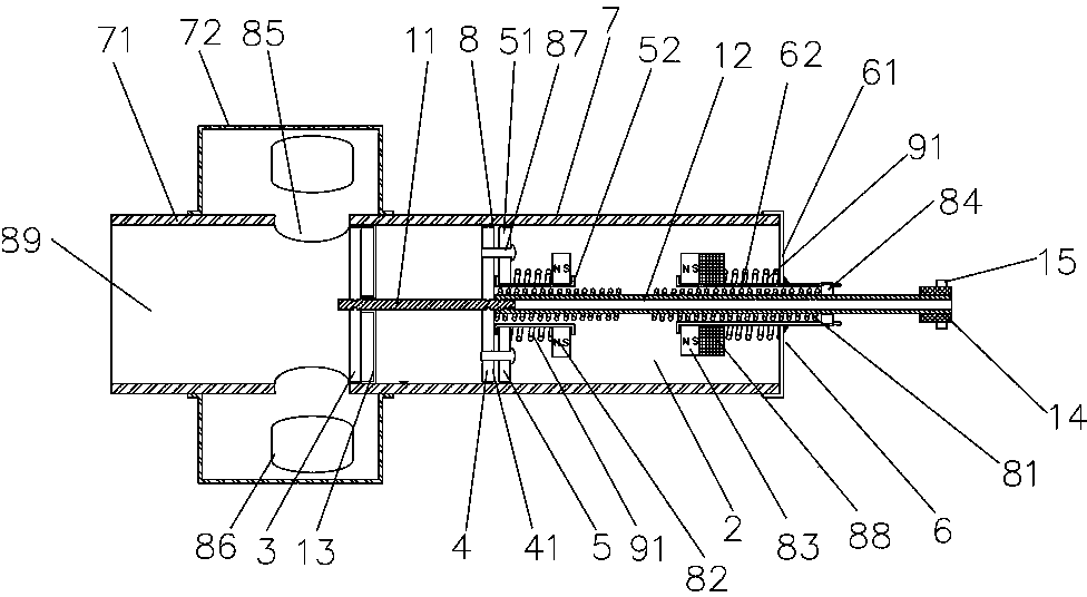
[0016] Reference Figure 1~2 , A control device for a variable valve exhaust pipe, comprising a main shaft 1 and a pipe body 7. The main shaft 1 is composed of a solid shaft 11 and a hollow shaft 12. Both the head and the tail end of the main shaft 11 are provided with grooves, and the hollow The shaft 12 is fixed on the pit of the solid shaft 11 by hydraulic pressure, so that the main shaft 1 forms a structure with a small front and a large rear, thereby reducing heat conduction, and the use of the hollow shaft 12 can further reduce heat conduction and reduce the stress of the control device main shaft 1. The weight reduces the inertia of motion, thereby increasing the service life of the spring 81 and improving the overall sensitivity of the control device. The solid shaft 11 is pressure-fixed with a piston plate 3 at the head end, and the solid shaft 11 and the hollow shaft 12 are fixedly provided with a supporting plate set 8 , The supporting piece group 8 includes a main s...


PUM


Abstract

A control device for a variable valve exhaust pipe, sleeved with a spring (81) between a mounting base (6) and a main support piece (4); the spring is located in a sleeve pipe (52) and extends into a mounting base sleeve pipe (62); both the sleeve pipe and the mounting base sleeve pipe are respectively provided with a magnet (82, 83) on the outer side; a fixing spring (91) is disposed between the magnet and an auxiliary support piece (5) or a mounting base casing (61), such that relatively high-temperature exhaust can be treated; the magnet and the mounting base casing are also provided with a magnetic coil (88) therebetween. On one hand, the length and compression space of the spring are increased, thus improving the adjustable exhaust range of the control device; on the other hand, by means of adding the magnetic coil, the magnetism magnitude of the magnet can be adjusted at any time, thus greatly improving the controllability of the device, therefore not only achieving an automatic maintenance effect and preventing the locking between a hollow shaft and an inner hollow pipe, but also increasing the magnetism of the magnet when the displacement needs to be increased abruptly during such situations as emergency acceleration, thus controlling the spring to quickly compress and open a piston plate to exhaust the gas.

Description

Technical field [0001] The invention relates to a motor vehicle exhaust pipe device, in particular to a control device for a variable valve exhaust pipe. Background technique [0002] Due to the current energy shortage, ordinary civilian cars will emphasize fuel saving. Therefore, engineers will increase the exhaust back pressure of the exhaust pipe by various means. This can increase the low-speed torque of the engine and reduce the fuel consumption of the car. It will also limit the maximum horsepower of the engine, because the exhaust pressure will increase greatly when the engine is outputting high horsepower. After the exhaust stroke, a large amount of exhaust gas remains in the cylinder, which will affect the intake efficiency of the next intake stroke. The airflow throughput of the engine is reduced, the rated maximum horsepower of the engine is severely reduced, and the acceleration response of the engine is relatively slow. Moreover, the increase in exhaust pressure wil...

Claims


Application Information

Patent Timeline
Patent Type & Authority Patents(China)
IPC IPC(8): F02D9/04
CPCF01N13/08F01N13/087F02D9/04
Inventor 冯子光
Owner 冯子光
Why Eureka
Try Eureka