
Full-light-field polarization aberration detection device and detection method

A detection device and full light field technology, which can be used in testing optical performance and other directions, and can solve problems such as complex algorithms and incomplete detection of polarization information.

Active Publication Date: 2012-07-25
SHANGHAI INST OF OPTICS & FINE MECHANICS CHINESE ACAD OF SCI
View PDF4 Cites 12 Cited by
  • Summary
  • Abstract
  • Description
  • Claims
  • Application Information

AI Technical Summary

Problems solved by technology

[0006] The purpose of the present invention is: in order to solve the problem of requiring a precision rotating mechanism to rotate in prior art 1, the problem of complex algorithm when the loading voltage in prior art 2 is a sinusoidal modulation voltage, and the problem of complex algorithm in prior art 1 and 2 There are problems that need to measure multiple times point by point and scan the full optical field, and the problems of incomplete detection of polarization information in prior technologies 3 and 4 provide a full optical field polarization aberration detection device and detection method , should have the characteristics of simple device structure, common optical axis and stability, measurement without mechanical rotation, simple algorithm, high spatial resolution and fast measurement speed

Method used


Image

  • Full-light-field polarization aberration detection device and detection method
  • Full-light-field polarization aberration detection device and detection method
  • Full-light-field polarization aberration detection device and detection method

Examples


Embodiment 1

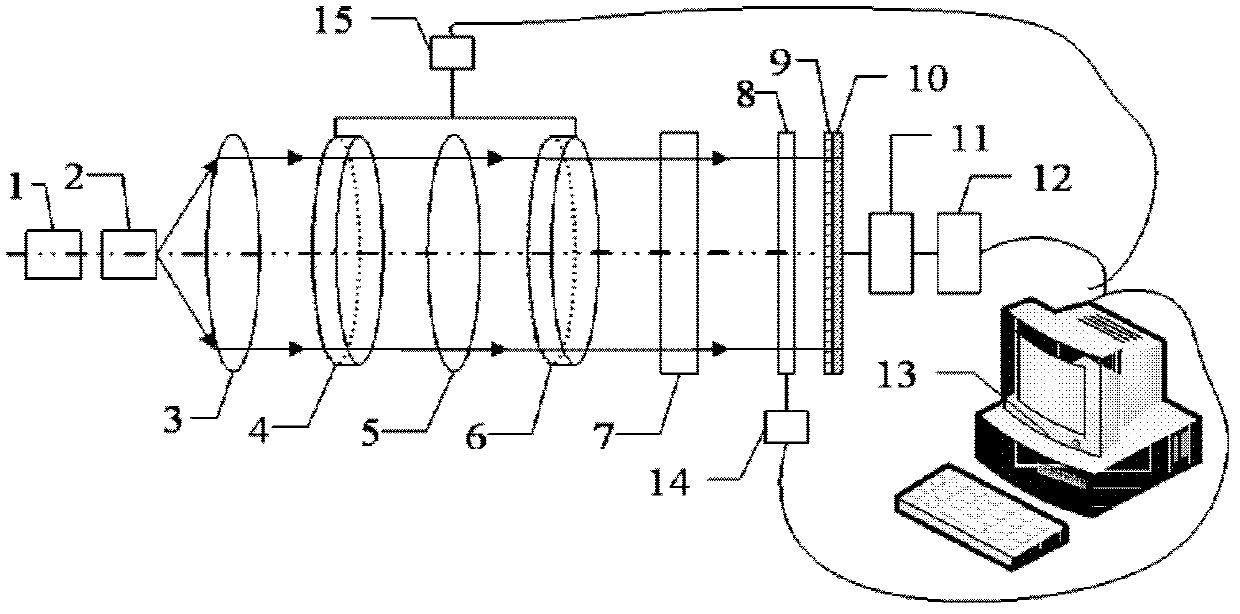
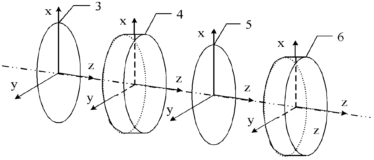
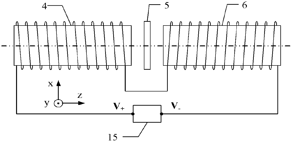
[0061] In order to measure the full optical field polarization aberration, an embodiment of the present invention provides a full optical field polarization aberration detection device, see figure 1 , the device includes: a full polarization generator PSG, a full polarization analyzer PSA and a signal processing and control system, the full polarization generator PSG includes a laser 1, a laser beam expander 2, a polarizer 3, a first Faraday rotator 4, 1 / 4 wave plate 5 and the second Faraday rotator 6, described full polarization state analyzer PSA comprises compensator 8, micropolarization analyzer array 9 and CCD detector array 10, described signal processing And control system comprises amplifier 11, synchronous data acquisition card 12, computer 13, first bias controller 14 and second bias controller 15, and its position relation is: along the parallel incident light beam that laser 1 produces , followed by the laser beam expander 2, polarizer 3, first Faraday rotator 4, 1...

Embodiment 2

[0073] In order to measure the full optical field polarization aberration information, the embodiment of the present invention provides a full optical field polarization aberration detection method based on the full optical field polarization aberration detection device for the sample 7 to be tested, see Figure 9 , it is characterized in that, this detection method comprises the following steps:

[0074] ①Change the magnitude of the bias control voltage loaded on the Faraday rotator, and perform the first measurement;

[0075] In order to facilitate reasoning and calculation, first introduce some basic knowledge related to polarization optics as follows:

[0076] When the fast axis direction angle of the linear phase retarder is α and the phase delay is 6, its Miller matrix is:

[0077] R α , δ = 1 0 ...


PUM

PropertyMeasurementUnit
Phase delayaaaaaaaaaa

Abstract

The invention discloses a full-light-field polarization aberration detection device and a full-light-field polarization aberration detection method. The device comprises a full polarization state generator (PSG), a full polarization state analyzer (PSA) and a signal processing and control system. The detection method comprises the following steps of: changing the magnitude of polarization control voltage applied to a Faraday rotator, and performing primary measurement; changing the magnitude of the polarization control voltage applied to the Faraday rotator, and performing secondary, tertiary and quaternary measurement; and processing primary, secondary, tertiary and quaternary measurement results according to an algorithm. The device and the method have the characteristics of simple device structure, optical coaxiality, stability, no need of mechanical rotation in measurement, simple algorithm, high spatial resolution and higher measurement speed.

Description

technical field [0001] The invention relates to the field of polarization aberration detection, in particular to an all-optical-field polarization aberration detection device and detection method. Background technique [0002] The use of optical components such as large numerical aperture projection objectives in high-precision imaging systems causes the incident wave to be seriously tilted off-axis, which makes the transmittance of TE and TM polarized light different, resulting in a serious decrease in imaging contrast. The full-field polarization aberration information of optical components such as large numerical aperture projection lenses is extracted and analyzed. [0003] The detection method for the extraction and analysis of the full optical field polarization aberration information is mainly based on the principle of the full optical field Miller matrix detection, through the detection of the full optical field Stokes parameters before and after the incident of the ...

Claims


Application Information

Patent Timeline
IPC IPC(8): G01M11/02
Inventor 曹绍谦步扬步鹏王向朝张敏汤飞龙李中梁
Owner SHANGHAI INST OF OPTICS & FINE MECHANICS CHINESE ACAD OF SCI
Learn More