Acoustic detection method for defects of cast iron material
A detection method and technology for material defects, applied in the direction of using sonic/ultrasonic/infrasonic waves to analyze solids, etc., can solve problems such as difficult application, shrinkage, slag inclusion, etc., to avoid economic losses and reduce coupling pressure.
- Summary
- Abstract
- Description
- Claims
- Application Information
AI Technical Summary
Problems solved by technology
Method used
Image

Examples
Embodiment 1
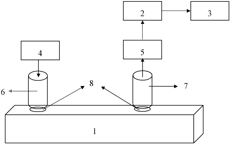
[0044] figure 1 It shows the configuration diagram of the acoustic detection system for cast iron material defects in this embodiment, 1 is the cast iron test plate, 2 is the acoustic emission detection module, 3 is the computer equipment, 4 is the pulse signal generation module, 5 is the amplifier, 6 is the excitation probe , 7 is the scanning probe, 8 is the couplant.
[0045] refer to figure 1 , the excitation probe 6 and the scanning probe 7 are fixed on the top of the cast iron test plate 1 by a clamp, wherein a coupling agent 8 is arranged between the excitation probe 6 and the cast iron test plate 1, and a coupling agent 8 is also arranged between the scanning probe 7 and the cast iron test plate 1 There is couplant 8. The pulse signal generation module 4 is connected with the excitation probe 6, and is used to transmit an ultrasonic excitation signal to the cast iron test plate 1 through the excitation probe 6, and the scanning probe 7 is used to receive the ultrason...
Embodiment 2
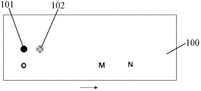
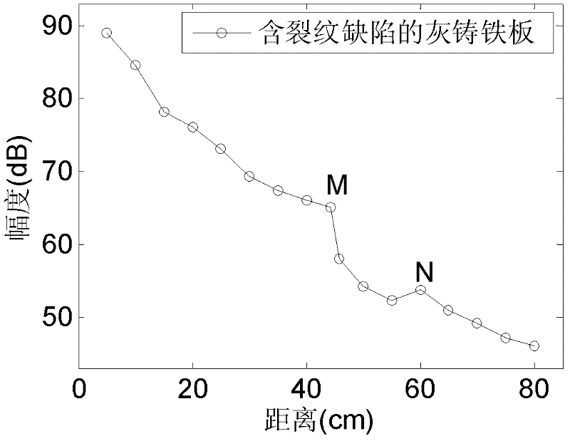
[0049] The applicant found in the research that when testing cast iron materials with crack defects, when the scanning probe is located in front of the defect, the attenuation characteristics are exactly the same as when there is no defect; when the scanning probe moves to the defect position and a certain range behind Within the range, the attenuation degree of the measured amplitude will be significantly larger than that of no defect; and after the scanning probe moves to a certain distance behind the defect, the amplitude will rise to the same attenuation level as that of no defect. degree; when the amplitude is raised to the normal attenuation level and continue to move the scanning probe backwards, the attenuation with defects and the attenuation without defects will be basically the same, specifically as figure 2 and image 3 shown.
[0050] refer to figure 2 and image 3 , the excitation probe 101 is fixed at the position of point O on the cast iron test plate 100 ...
PUM
| Property | Measurement | Unit |
|---|---|---|
| Thickness | aaaaa | aaaaa |
| Length | aaaaa | aaaaa |
Abstract
Description
Claims
Application Information
 - Generate Ideas
- Intellectual Property
- Life Sciences
- Materials
- Tech Scout
- Unparalleled Data Quality
- Higher Quality Content
- 60% Fewer Hallucinations
Browse by: Latest US Patents, China's latest patents, Technical Efficacy Thesaurus, Application Domain, Technology Topic, Popular Technical Reports.
© 2025 PatSnap. All rights reserved.Legal|Privacy policy|Modern Slavery Act Transparency Statement|Sitemap|About US| Contact US: help@patsnap.com