Optical pulse position modulating signal receiver and data processing method thereof

A technology for modulating signals and receivers, which is applied in the field of receiving optical pulse modulated signals to achieve the effects of easy adjustment and setting, high clock frequency and good scalability.

Active Publication Date: 2012-07-25
NANJING INST OF ADVANCED LASER TECH
View PDF5 Cites 1 Cited by
  • Summary
  • Abstract
  • Description
  • Claims
  • Application Information

AI Technical Summary

Problems solved by technology

[0009] The problem to be solved by the present invention is to overcome the above-mentioned problems faced by the traditional hard receiver and the computer-based receiving and processing system in the application of free space optical communication, and provide an optical pulse position A modulated signal receiver and its data processing method. This receiver can solve the receiving, demodulating and decoding problems of OPPM based on RS code under different channels, background noise and pulse distortion. The receiver has fast operation speed, high reliability, Easy to use, good scalability, suitable for free space optical communication and other fields

Method used


Image

  • Optical pulse position modulating signal receiver and data processing method thereof
  • Optical pulse position modulating signal receiver and data processing method thereof
  • Optical pulse position modulating signal receiver and data processing method thereof

Examples


Embodiment Construction

[0046]The device of the present invention takes the free space laser communication in a certain situation as an embodiment, and adopts the hexadecimal optical pulse position modulation mode and RS (15, 9) code. Expected background noise light and detector internal noise are averaged μ at the ADC input n is 500mV, standard deviation σ n It is a voltage signal of 100mV; the received signal pulse width is 500ns, and the signal pulse is converted into an average value at the ADC input end of the analog-to-digital converter, respectively μ p 500, 3500, 4500, 2500, 500mV, the standard deviation is σ p is a voltage signal sequence of 100mV. The present invention will be further described below with reference to specific embodiments and accompanying drawings, but the protection scope of the present invention should not be limited by this.

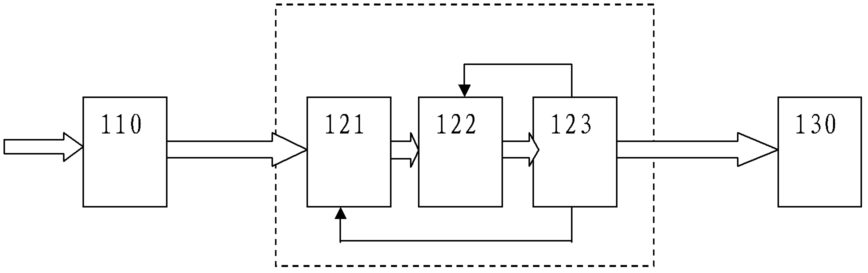
[0047] First, please refer to figure 1 , figure 1 It is a schematic diagram of the overall structure of the optical pulse position modulation...


PUM


Abstract

An optical pulse position modulating signal receiver and a data processing method thereof are applicable to free space optical communication. The optical pulse position modulating signal receiver consists of a photoelectric multiplier tube, an electric signal processing module and a liquid crystal display, wherein the electric signal processing module consists of an analog digital converter, a first-in-first-out array and a digital signal processor, the photoelectric multiplier tube receives optical signals to convert the optical signals to simulated electric signals, the simulated electric signals are converted into digital signals by the analog digital converter (ADC), are input into a DSP (digital signal processor) through the first-in-first-out (FIFO) array, the DSP performs filter matching, threshold judgment, frame detection and quick RS (radio station) code decoding for the digital signals and transmits corrected information to be displayed on the liquid crystal display. The optical pulse position modulating signal receiver can solve the problem that modulation and demodulation signals can be received on the basis of optical pulse position modulating signals of RS codes under the environment of different signal channels, and is high in computing speed and reliability, convenient in use and fine in expansibility.

Description

technical field [0001] The present invention relates to the reception of optical pulse modulation signal (OPPM for short), in particular to an optical pulse position modulation signal receiver based on Reed-Solomon code (RS code for short) and a data processing method thereof. Background technique [0002] With the continuous development of pulsed lasers, lasers are more and more widely used in the field of optical communication, among which optical fiber communication has high transmission speed, low cost and rapid development. However, it is not suitable for connectionless space communication and communication between moving objects due to the need to realize the connection of optical fibers on the physical link. Based on free space optical communication, it not only avoids the requirement for physical connection of optical fiber communication, but also reduces the communication cost, and has good confidentiality. When the laser propagates in the atmosphere, due to the in...

Claims


Application Information

Patent Timeline
Patent Type & Authority Applications(China)
IPC IPC(8): H04B10/158H04B10/524H04B10/69
Inventor 朱小磊胡秀寒周田华贺岩陈卫标
Owner NANJING INST OF ADVANCED LASER TECH
Why Eureka
Try Eureka