
Hardware-based RS485 (radio sensing 485) automatic transceiving control method and circuit

A RS485, automatic transceiver technology, applied in the direction of duplex signal operation, can solve the problems of reducing bus anti-interference ability, increasing system power consumption, no driving ability, etc., to improve real-time and anti-interference ability, and improve electromagnetic compatibility. capability, the effect of improving system reliability

Inactive Publication Date: 2012-07-25
CRRC DALIAN CO LTD
View PDF3 Cites 20 Cited by
  • Summary
  • Abstract
  • Description
  • Claims
  • Application Information

AI Technical Summary

Problems solved by technology

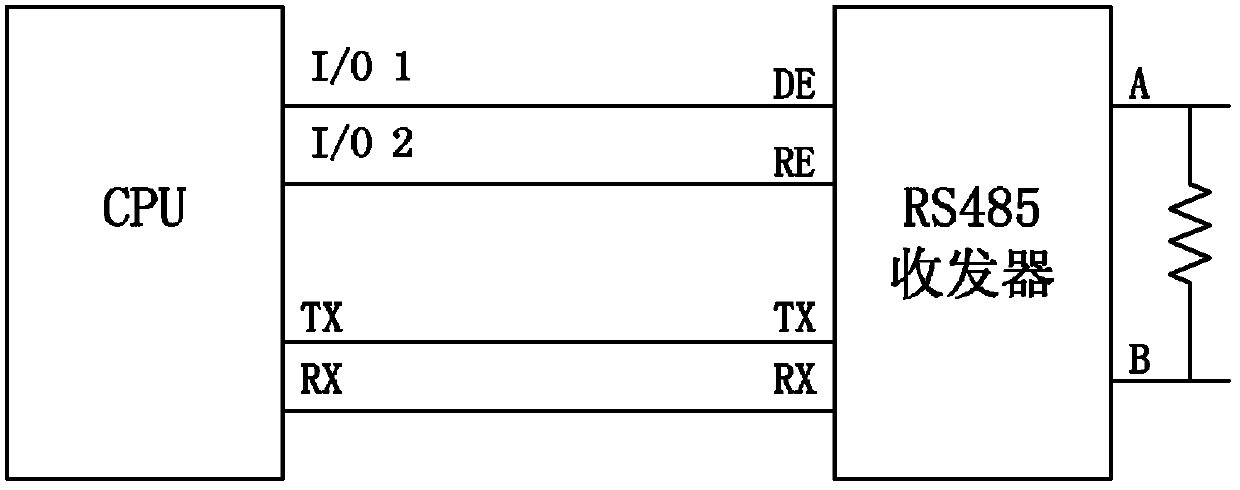
[0006] 1. Occupy the I / O pin resources of the CPU
[0007] 2. There is a certain delay between the assignment of software to the CPU port and the actual enabling of sending data. If the timing of the conversion from sending to receiving is improper, data will be lost and the data frame will be incomplete;
[0008] 3. The reliability of the transition between receiving and sending states is affected by the CPU state of any node, which cannot guarantee that the system has good anti-interference performance
If the CPU of a node on the bus fails, and it is in the high-level state of RS485 transmission, the rest of the nodes will not be able to use the RS485 bus communication normally
[0009] 4. Using this solution in a multi-threaded operating environment with an operating system will increase the difficulty of developing embedded programs
[0012] 2. When this circuit sends a high level, all interfaces on the bus are in the receiving state, and the bus is idle, allowing other interfaces to send data, so it is easy to introduce bus conflicts
[0013] 3. When this circuit sends high level, the transmitter is in a high-impedance state, and there is no driving current, so there is no driving capability, which reduces the anti-interference ability of the interface to a certain extent
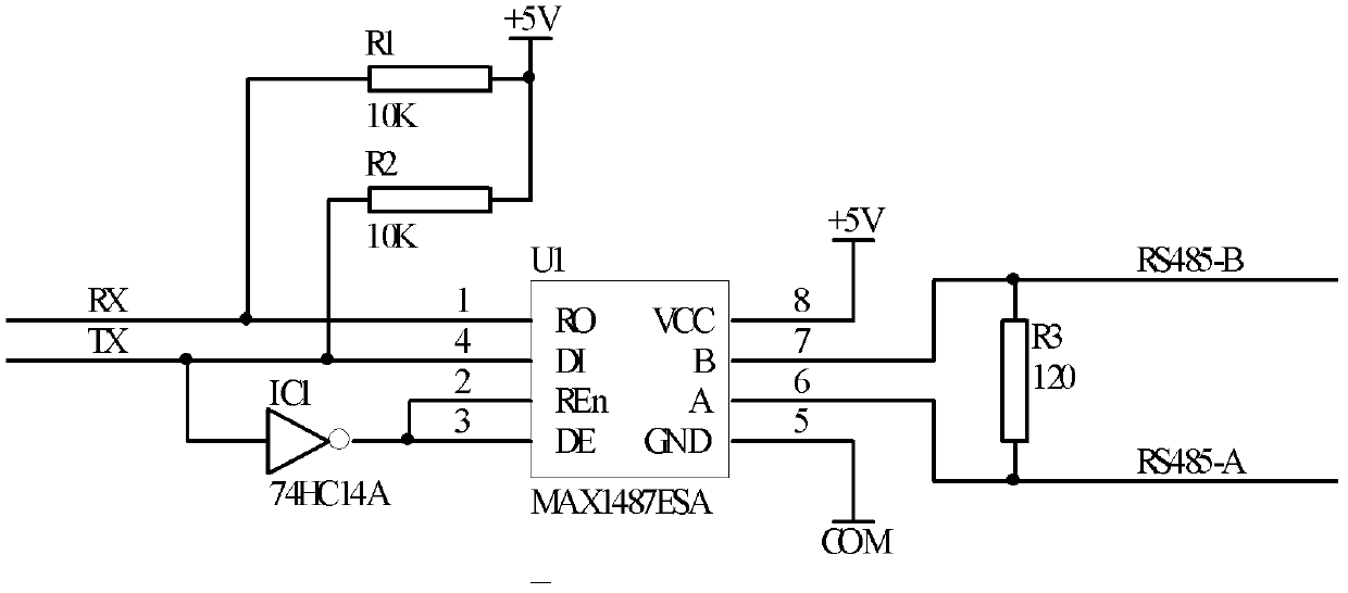
[0015] 1. In order to make TX = 1, under the action of the pull-up and pull-down resistors, the bus is at a high level. To achieve this level, the pull-up and pull-down resistors must be comparable to the terminal matching resistor (120 ohms) ( That is, the resistance value is similar), so the power consumption of the system is increased, and the load of the first-off resistor is increased, which reduces the thermal reliability
[0016] 2. When TX=0, the level between AR is negative, which further increases the power consumption of the resistance and further reduces the reliability
[0017] 3. Due to the existence of pull-up and pull-down resistors, the impedance of the bus is changed, which reduces the anti-interference ability of the RS485 bus and the number of nodes that the bus can support; at the same time, the pull-up and pull-down resistors have limited driving capabilities, which will further reduce the bus. Anti-interference ability
[0020] 1. The baud rate setting interface is connected through the CPU parallel port, which still requires additional CPU port resources and computing resources
[0021] 2. Additional control logic algorithms and real-time control algorithms for the baud rate setting interface need to be added to the control software, which increases the load on the CPU
When the system interference is serious, or when the CPU and CPLD are powered on and started asynchronously, when the trigger edge of the count enable signal matches or coincides with the TX signal, it will cause the transmission commutation control to be at the end of the previous frame and the beginning of the next frame. Collisions will increase the bit error rate and reduce the reliability of the bus

Method used


Image

  • Hardware-based RS485 (radio sensing 485) automatic transceiving control method and circuit
  • Hardware-based RS485 (radio sensing 485) automatic transceiving control method and circuit
  • Hardware-based RS485 (radio sensing 485) automatic transceiving control method and circuit

Examples


Embodiment Construction

[0039] In order to make the purpose, technical solutions and advantages of the embodiments of the present invention clearer, the technical solutions in the embodiments of the present invention will be clearly and completely described below in conjunction with the drawings in the embodiments of the present invention. Obviously, the described embodiments It is a part of embodiments of the present invention, but not all embodiments. Based on the embodiments of the present invention, all other embodiments obtained by persons of ordinary skill in the art without making creative efforts belong to the protection scope of the present invention.

[0040] see Figure 4 . In this embodiment, the inverting circuit adopts a logical NOT gate; the clock generating circuit is composed of a Schmitt trigger (4093), a resistor R1, and a capacitor C1; the counting circuit adopts a counter (4024); the trigger circuit adopts a D flip-flop (4013 ). The input terminal of the logic NOT gate is conn...


PUM


Abstract

The invention relates to an RS485 automatic transceiving control method and circuit. An inverting circuit transmits an inverted TX (transmit) signal to the reset (RST) end of a counting circuit and to the R end of a trigger; a clock generation circuit generates clock frequency fixed to a serial communication Baud rate, and transmits the clock frequency to the CLK (clock) end of the counting circuit; the output end of the counting circuit is connected with the S end of the trigger; and the output end of the trigger is connected with the enable end (DE) of RS485. When the TX signal changes from a higher level value to a lower level value, the circuit transmits a high-level enable signal to the DE port of the RS485 chip to start data transmission; when the TX signal changes from a lower level value to a higher level value, a timer starts and keeps the high-level enable signal of the DE port of the RS485 chip; and the circuit transmits a low-level transmission stop signal to the DE port of the RS485 chip to stop the data transmission if the high-level retention time of the TX signal exceeds the number of frame beats of serial communication information. According to the invention, the RS485 automatic transceiving method and circuit can save the port resources of CPU (central processing unit), and improve communication real-time performance, the interference resistance and the electromagnetic compatibility of the entire system communication.

Description

technical field [0001] The invention belongs to the field of RS485 field bus control, in particular to a hardware-based RS485 automatic transceiver control method and circuit. Background technique [0002] As an electrical specification for data transmission, the suggested standard RS485 is applicable due to its simple network structure interface, convenient control, low cost, strong ability to resist common mode interference, long transmission distance at an appropriate baud rate, and easy network expansion. It is widely used in many different fields, especially in the industrial field as a data transmission link. [0003] The RS485 communication interface circuit adopts differential level transmission and works as half-duplex. Its main function is to convert the TX transmission signal into a differential signal in the communication network through the "transmitter", and also convert the differential signal in the communication network into an RX reception signal through t...

Claims


Application Information

Patent Timeline
IPC IPC(8): H04L5/16
Inventor 蔡志伟管明华孙宗琳邰明辉
Owner CRRC DALIAN CO LTD
Learn More