Thin-film solar cell and manufacturing method therefor
A solar cell and thin film technology, applied in circuits, photovoltaic power generation, electrical components, etc., can solve the problems of too much bending of the scribe line, longer current path, larger Joule loss, etc., so as to improve power generation efficiency and reduce electric field strength. The effect of increasing and suppressing Joule loss
- Summary
- Abstract
- Description
- Claims
- Application Information
AI Technical Summary
Problems solved by technology
Method used
Image
Examples
Embodiment approach 1
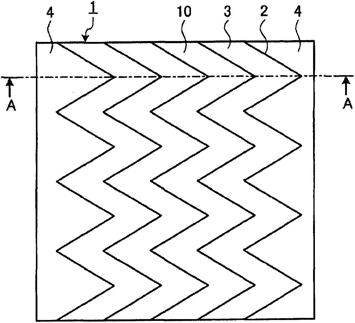
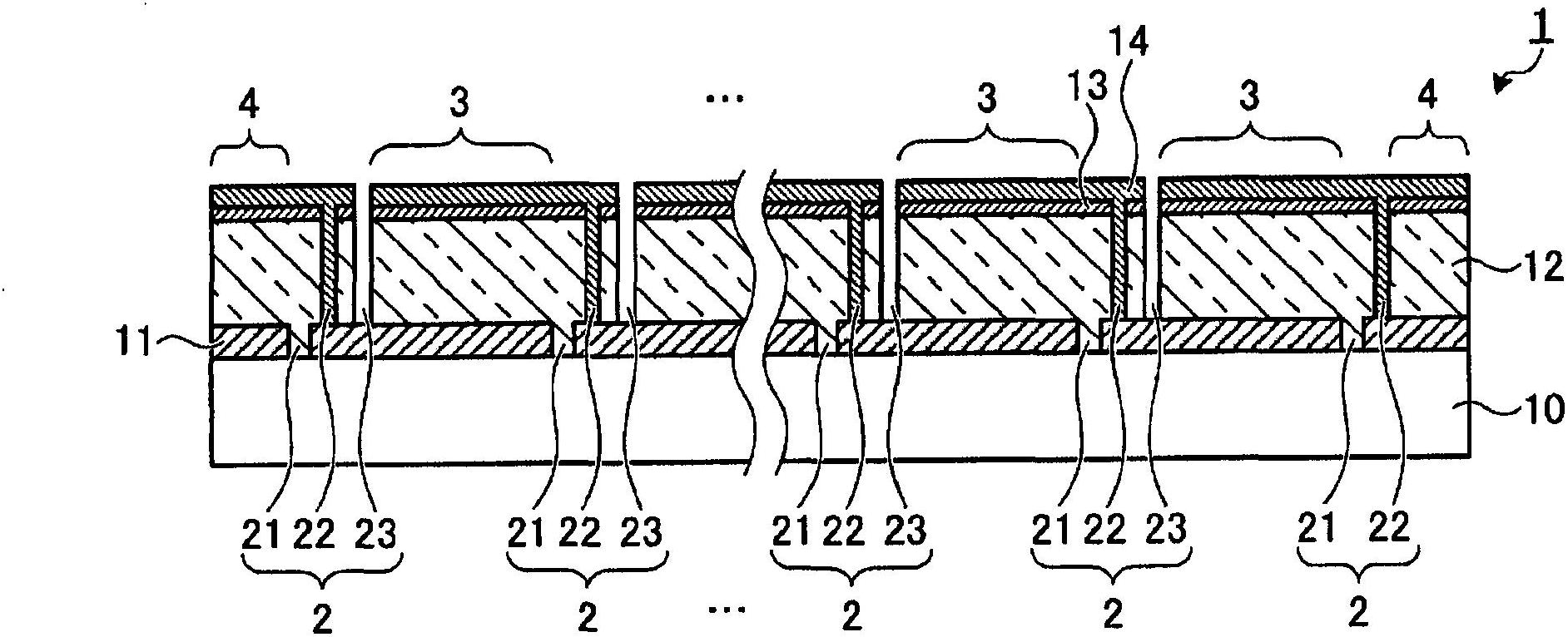
[0041] figure 1It is a plan view showing an example of the thin-film solar cell according to Embodiment 1 of the present invention. The thin-film solar cell 1 according to Embodiment 1 is integrated by connecting a plurality of unit solar cells 3 in series on a rectangular insulating and translucent substrate 10 , thereby functioning as a thin-film solar cell module as a whole. Furthermore, the current led to the current extraction parts 4 at both ends is extracted to the outside. Here, between the unit solar cells 3 and between the unit solar cells 3 and the current extraction part 4, they are separated by the scribe line 2 as a separation groove. Combinations of line segments whose end faces of the optical substrate 10 are inclined are periodically repeated in a curved shape, and adjacent scribe lanes 2 are arranged substantially parallel to each other. In addition, the unit solar cell 3 has a shape in which the direction along the scribed lane 2 becomes the lengthwise dir...
Embodiment approach 2
[0127] Figure 16 It is a plan view showing an example of the thin-film solar cell according to Embodiment 2 of the present invention. Thin-film solar cell 1 according to Embodiment 2 has a structure in which scribe lanes 2 are arranged with a degree of curvature decreasing from the center of insulating translucent substrate 10 toward the edge (end) of the width direction of scribe lane 2 . In this example, the shape of the scribe line 2 separating the unit solar cell 3 and the current extraction part 4 at both ends in the width direction is substantially parallel to the end surface of the insulating translucent substrate 10 . In addition, since the degree of curvature of adjacent scribe lanes 2 at the edge varies, they are not substantially parallel, but the positions and periods of the peaks and valleys constituting the curved portion are consistent. Accordingly, it is possible to suppress occurrence of a site where the amount of change in the width of the unit solar batter...
Embodiment approach 3
[0132] Figure 17 It is a plan view showing an example of the thin-film solar cell according to Embodiment 3 of the present invention. In the thin-film solar cell 1 according to Embodiment 3, the degree of curvature of the scribe lane 2 does not change even at the edge (end) of the scribe lane 2 in the width direction. When the scribed lane 2 at the end is intended to be substantially parallel to the adjacent scribed lane 2 , it will protrude from the insulating translucent substrate 10 . Therefore, the curved portion of the endmost scribe line 2 protruding from the insulating and translucent substrate 10 is parallel to the end surface of the insulating and translucent substrate 10 so as to converge in the insulating and translucent substrate 10 . In addition, the shape of the scribed lane 2 is changed so that the unit solar cells 3 arranged at both ends in the left-right direction of the drawing (the width direction of the scribed lane 2 ) have approximately the same area as...
PUM
 Abstract
Description
Claims
Application Information
 - R&D
- Intellectual Property
- Life Sciences
- Materials
- Tech Scout
- Unparalleled Data Quality
- Higher Quality Content
- 60% Fewer Hallucinations
Browse by: Latest US Patents, China's latest patents, Technical Efficacy Thesaurus, Application Domain, Technology Topic, Popular Technical Reports.
© 2025 PatSnap. All rights reserved.Legal|Privacy policy|Modern Slavery Act Transparency Statement|Sitemap|About US| Contact US: help@patsnap.com


