Dedusting-denitrating integrated device

A denitrification catalyst and denitrification technology, applied in chemical instruments and methods, dispersed particle separation, dispersed particle filtration, etc., can solve problems such as increased control area, SCR catalyst bed wear, catalyst life reduction, etc., to achieve structure and control system Simple, improve the overall denitrification efficiency, and prevent the effect of catalyst sintering

Active Publication Date: 2012-08-01
HUNAN UNIV
View PDF1 Cites 17 Cited by
  • Summary
  • Abstract
  • Description
  • Claims
  • Application Information

AI Technical Summary

Problems solved by technology

However, when the cross-sectional area of ​​the flue is large, the control area will become more or larger, resulting in the complexity of the operating system or the increase of the material conveying distance, thus affecting the required NH 3 Realization of / NO ratio
If the shape of the flue is circular or other special shapes, there may be dead corners of ammonia injection, which will seriously affect the NO x The overall removal efficiency of
At the same time, the ordinary SCR denitrification device has a short ammonia mixing stroke, which is not conducive to NH 3 with NO x Fully mixed, if the ammonia mixing stroke is longer, it will take up space on the one hand, and on the other hand, the heat loss of the flue gas will be greater
In addition, the traditional SCR denitrification process mainly adopts high-temperature and high-dust arrangement, and the flue gas contains a lot of dust, which is easy to cause wear, blockage and poisoning of the SCR catalyst bed, and the direct entry of high-temperature flue gas into the catalyst may also cause the catalyst to be sintered and deactivated. Catalyst life is reduced, equipment maintenance rate is increased, and cost is increased

Method used


Image

  • Dedusting-denitrating integrated device
  • Dedusting-denitrating integrated device
  • Dedusting-denitrating integrated device

Examples


Embodiment Construction

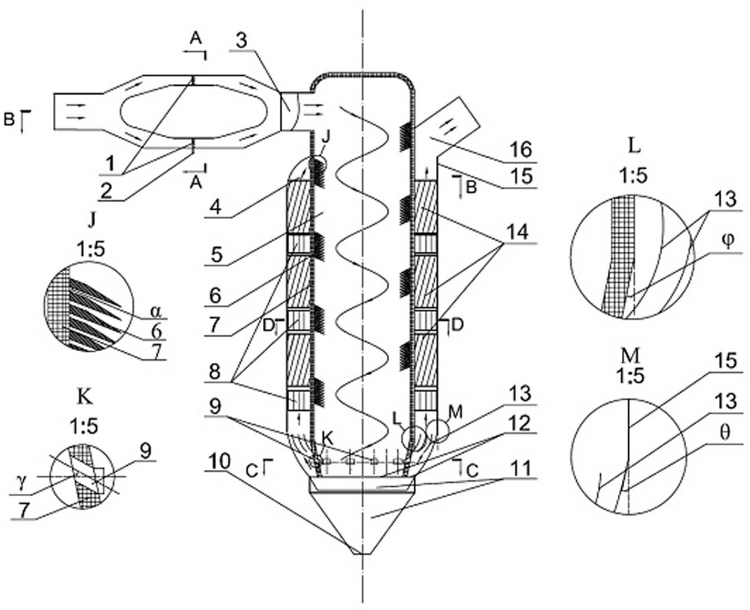
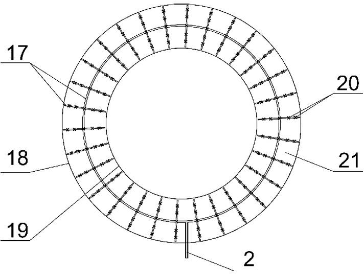
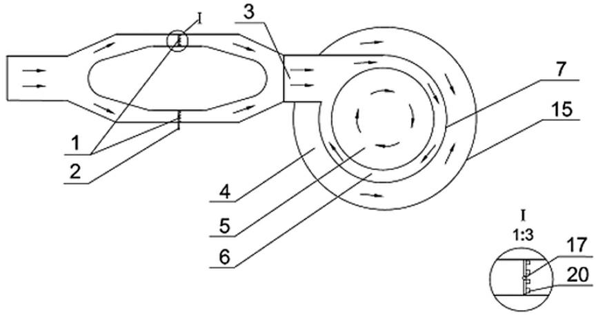
[0028] Such as Figure 1 to Figure 5 As shown, the dust removal and denitrification integrated device includes a flue gas channel 21, a mixed flue gas inlet 3, a housing composed of an outer cylinder 4 and an inner cylinder 5, an ash hopper 11 at the bottom of the housing, the flue gas channel 21 and the mixed flue gas The gas inlet 3 is connected, the mixed flue gas inlet 3 is connected with the shell, and there is an annular gap between the outer cylinder wall 15 and the inner cylinder wall 7, and the denitration catalyst bed 14 that is uniformly distributed radially is arranged in the annular gap, and the outer The cylinder 4 communicates with the inner cylinder 5 through the Venturi channel 9, the flue gas channel 21 is annular in cross section, and the flue gas channel 21 is provided with radially distributed ammonia injection grids 1, the ammonia injection grids 1 include ammonia Pipeline 17 and ammonia injection nozzles 20 radially distributed in flue gas passage 21 alon...


PUM


Abstract

The invention discloses a dedusting-denitrating integrated device which comprises a flue gas channel, a mixed flue gas inlet and a shell consisting of an outer cylinder and an inner cylinder, and a ash hopper at the bottom of the shell, wherein the inner cylinder is mainly used for dedusting and ammonia mixing, the outer cylinder is mainly used for containing a denitrating catalyst bed, the crosssection of the flue gas channel is ring-shaped, and ammonia spray grilles are distributed in the flue gas channel in a radial manner so that the required NH3-to-NO ratio can be reached more easily. The device provided by the invention can be used for dedusting before carrying out denitrating, a catalyst can be effectively prevented from being worn, poisoned and blocked and the service life of thecatalyst can be prolonged. Under the condition that the length of the device is not increased, the ammonia mixing time is prolonged and ammonia mixing can be performed fully; heat absorbing spiral plates and cooling rectifier plates are arranged in both the inner cylinder and the outer cylinder to share heat of flue gas at the inlet, and therefore the heat loss of flue gas can be reduced, the denitrating efficiency can be improved and the catalyst is prevented from being sintered and inactivated under the action of superheated flue gas.

Description

technical field [0001] The invention belongs to the field of environmental protection, is suitable for purifying boiler flue gas and industrial tail gas, and in particular relates to an integrated device for dust removal and denitrification of flue gas. Background technique [0002] NO x It is one of the important reasons that directly lead to acid rain, the hole in the ozone layer and photochemical smog, and the wanton emission of NO x Will cause serious harm to human health and the ecological environment, so NO x Governance has always been the focus of the world's environmental protection field. countries around the world to NO x The emission standards of NO x The discharge of the gas has also begun to implement stricter standards than in the past, which undoubtedly has higher requirements for the flue gas denitrification technology. Therefore, the flue gas denitrification technology must be continuously improved. [0003] For NO in flue gas x The removal of selecti...

Claims


Application Information

Patent Timeline
Patent Type & Authority Applications(China)
IPC IPC(8): B01D53/90B01D53/56B01D46/02
Inventor 李彩亭文青波方鑫赵亚培肖育军
Owner HUNAN UNIV
Why Eureka
Try Eureka