Automatic welding method for microdeformation of cylinder sleeve of bottom upright of large hydraulic support

A hydraulic support and automatic welding technology, which is applied in the direction of welding medium, welding equipment, welding equipment, etc., can solve the problems of high heat input, large deformation, and unreachable pistons, and achieve high laser energy input, fast welding speed, and improved The effect of work efficiency

Inactive Publication Date: 2012-08-01
LIAONING TECHNICAL UNIVERSITY
6 Cites 3 Cited by

AI-Extracted Technical Summary

Problems solved by technology

However, due to the continuous high heat input during the welding process, the deformation after welding cannot be effectively controlled, and the deformation (ellipticity) is less than or equal to 0.3mm
[0007] In the welding process of the above welding method, the heat input is large and the heat accumulation is large, which makes the heat-affected zone of the weldment large, and will generate a large binding force after welding, which is easy to cause local stress concentration and large deformation.
Even if post-heat treatment is carried out af...

Abstract

The invention discloses an automatic welding method for the microdeformation of a cylinder sleeve of a bottom upright of a large hydraulic support, belonging to the technical field of laser welding and relating to a welding method for a cylinder sleeve of a bottom upright of a hydraulic support, in particular to a self-fluxing high-energy rapid laser input welding method capable of controlling deformation in a welding process. The automatic welding method for the microdeformation of the cylinder sleeve of the bottom upright of the large hydraulic support, provided by the invention, can be used for effectively controlling the deformation after the cylinder sleeve is welded, so that the stroke of the bottom upright of the hydraulic support is up to the maximum. The method is carried out according to the following steps of: fixing a to-be-welded cylinder sleeve of the bottom upright of the hydraulic support and a base of the cylinder sleeve on a chuck of a numerical control machine tool; filling iron-base alloy powder into a powder feeding device coaxial with the optical axis of a laser beam of a laser; setting the parameter of the powder feeding device and the laser welding parameter of the laser; and starting the laser, the powder feeding device and the numerical control machine tool to automatically finish the welding process.

Application Domain

Technology Topic

High energyIron based alloy +6

Image

  • Automatic welding method for microdeformation of cylinder sleeve of bottom upright of large hydraulic support

Examples

  • Experimental program(3)

Example Embodiment

[0025] Example 1:
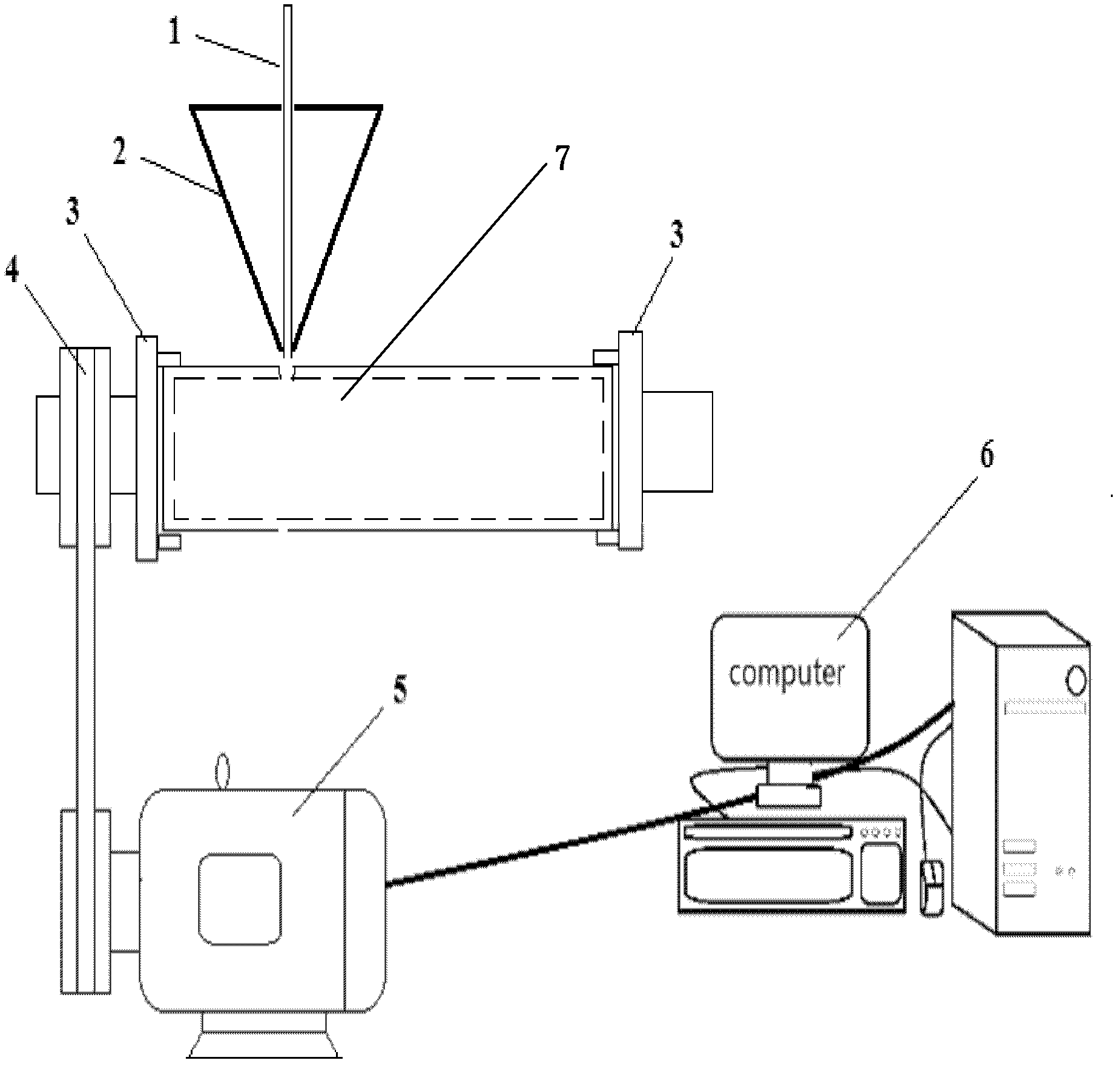
[0026] An automatic welding method for micro-deformation of the cylinder liner of the bottom column of a large hydraulic support, which is carried out according to the following steps:
[0027] Step 1: Fix the hydraulic support bottom column cylinder liner and its base to be welded on the chuck of the CNC machine tool;
[0028] Step 2: Loading the iron-based alloy powder into a powder feeding device coaxial with the optical axis of the laser beam of the laser;
[0029] Step 3: Set the parameters of the powder feeding device and the laser welding parameters of the laser;
[0030] Laser welding parameters of the laser: the laser power is 2000W, and the welding speed is 3mm/s;
[0031] Powder feeding device parameters: powder feeding volume is 230g/min;
[0032] Step 4: Turn on the laser, powder feeding device and CNC machine tool at the same time to automatically complete the welding process.
[0033] The composition of the iron-based alloy powder described in step 2 is (%):
[0034] C: 0.5, Ni: 28.0, Cr: 13.0, B: 1.0, Si: 2.5, Mo: 3.5, and the balance is Fe.
[0035] After welding, measure the deformation (ellipticity) of the cylinder liner to be 0.080mm.

Example Embodiment

[0036] Example 2:
[0037] An automatic welding method for micro-deformation of the cylinder liner of the bottom column of a large hydraulic support, which is carried out according to the following steps:
[0038] Step 1: Fix the hydraulic support bottom column cylinder liner and its base to be welded on the chuck of the CNC machine tool;
[0039] Step 2: Loading the iron-based alloy powder into a powder feeding device coaxial with the optical axis of the laser beam of the laser;
[0040] Step 3: Set the parameters of the powder feeding device and the laser welding parameters of the laser;
[0041] Laser welding parameters of the laser: the laser power is 2500W, and the welding speed is 5mm/s;
[0042] Powder feeding device parameters: powder feeding volume is 248g/min;
[0043] Step 4: Turn on the laser, powder feeding device and CNC machine tool at the same time to automatically complete the welding process.
[0044] The composition of the iron-based alloy powder described in step 2 is (%):
[0045] C: 0.5, Ni: 30, Cr: 5.0, B: 1.5, Si: 3.0, Mo: 2.0, and the balance is Fe.
[0046] After welding, the deformation (ellipticity) of the cylinder liner is measured to be 0.075mm.

Example Embodiment

[0047] Example 3:
[0048] An automatic welding method for micro-deformation of the cylinder liner of the bottom column of a large hydraulic support, which is carried out according to the following steps:
[0049] Step 1: Fix the hydraulic support bottom column cylinder liner and its base to be welded on the chuck of the CNC machine tool;
[0050] Step 2: Loading the iron-based alloy powder into a powder feeding device coaxial with the optical axis of the laser beam of the laser;
[0051] Step 3: Set the parameters of the powder feeding device and the laser welding parameters of the laser;
[0052] Laser welding parameters of the laser: the laser power is 3000W, and the welding speed is 6mm/s;
[0053] Powder feeding device parameters: powder feeding volume is 258g/min;
[0054] Step 4: Turn on the laser, powder feeding device and CNC machine tool at the same time to automatically complete the welding process.
[0055] The composition of the iron-based alloy powder described in step 2 is (%):
[0056] C: 1.0, Ni: 10, Cr: 15.0, B: 3.5, Si: 4.0, and the balance is Fe.
[0057] After welding, the deformation (ellipticity) of the cylinder liner is measured to be 0.095mm.
[0058] It is worth noting that: when fixing the cylinder liner and its base on the chuck of the CNC machine tool, it must be possible to make the cylinder liner and its base of the bottom column of the hydraulic support close together to prevent the iron-based alloy powder from escaping after being sent out. .
[0059] The powder feeding device is combined with a vertical loading and unloading split laser cladding coaxial powder feeding nozzle.
[0060] The welded seam of the cylinder liner and its base after welding is a self-fluxing boss, and the boss in the weld area is hoop-shaped, and the axial dimension of the boss is 0.9 to 1.2 times the wall thickness of the cylinder liner of the bottom column of the hydraulic support.

PUM

no PUM

Description & Claims & Application Information

We can also present the details of the Description, Claims and Application information to help users get a comprehensive understanding of the technical details of the patent, such as background art, summary of invention, brief description of drawings, description of embodiments, and other original content. On the other hand, users can also determine the specific scope of protection of the technology through the list of claims; as well as understand the changes in the life cycle of the technology with the presentation of the patent timeline. Login to view more.

Similar technology patents

Classification and recommendation of technical efficacy words

Why Eureka
Try Eureka