
Method and apparatus for machining based on titled laser scanning

A processing method and technology of processing equipment, applied in the field of laser processing methods and equipment, can solve the problems of laser processing method limitation, uneven surface or micro-cracks, slow processing speed, etc., and achieve the effect of enhancing the quality of cutting and scribing

Inactive Publication Date: 2012-08-01
AXIATA
View PDF7 Cites 6 Cited by
  • Summary
  • Abstract
  • Description
  • Claims
  • Application Information

AI Technical Summary

Problems solved by technology

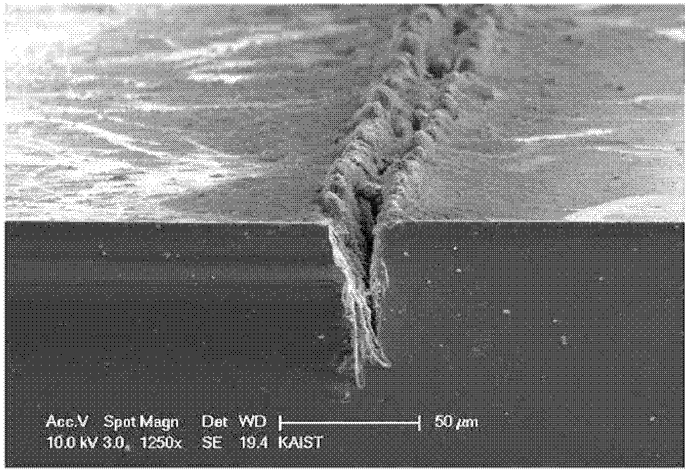
[0003] However, laser processing also has several problems in that particles are generated at the portion of the workpiece to which the laser beam is irradiated, and the surface of the workpiece becomes rough and uneven due to resolidification of the modified portion of the workpiece (like figure 1 shown in ), and the laser beam is prevented from reaching deeper parts of the workpiece due to particle interference with scribing so that the laser beam is re-radiated to make the processed part deeper
For this reason, when a sufficient scoring depth cannot be secured, there is a problem that the workpiece cracks in a direction different from the scoring direction, and therefore, the laser processing method has limitations in application
[0004] In addition, with the development of laser manufacturing technology, high-power picosecond lasers or femtosecond lasers have been developed, but in the case where these lasers are used for cutting or scribing, irregular microcracks are attributed to Amorphization due to thermal influence of the processing surface or due to volume expansion due to evaporation is formed on the surface of the plate and makes the surface of the cutting area rough and deteriorates the characteristics of the components produced on the surface of the workpiece
[0005] In order to minimize these effects, a method of repeatedly irradiating relatively weak pulsed laser beams to the surface of a workpiece has recently been employed, but it also has limitations in solving problems of uneven surfaces or microcracks due to resolidification, and Does not provide efficient and fast processing using high power lasers
In addition, since laser is used in the scribing method, there is a method of modifying the internal structure of the workpiece by collecting the laser beam inside the workpiece, but this method also has several problems in that, when the method There are limitations when applied to thick workpieces because the method produces pre-configured cutting points or lines inside the workpiece by irradiating the laser in the vertical direction to the surface of the workpiece; and the problem is that even if the method is suitable for thick The workpiece must also irradiate the laser repeatedly, so the processing speed is slow

Method used


Image

  • Method and apparatus for machining based on titled laser scanning
  • Method and apparatus for machining based on titled laser scanning
  • Method and apparatus for machining based on titled laser scanning

Examples


Embodiment Construction

[0025] The above and other objects, features and advantages of the present invention will be apparent from the following detailed description of preferred embodiments of the present invention taken in conjunction with the accompanying drawings.

[0026] Reference will now be made in detail to preferred embodiments of the present invention with reference to the accompanying drawings, but the invention is not limited or limited by these embodiments.

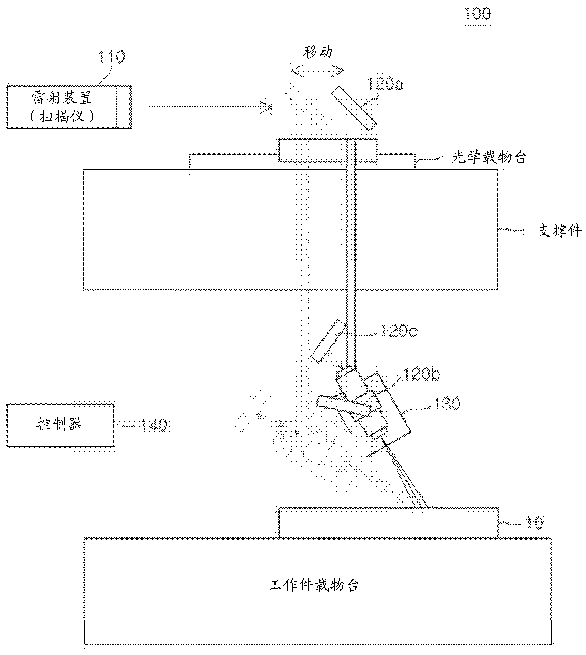
[0027] figure 2 It is a schematic diagram for describing a laser processing device 100 according to a preferred embodiment of the present invention.

[0028] see figure 2 , the laser processing equipment 100 according to the present invention includes a laser device 110 , a first optical system 120 having a first mirror 120 a , a second mirror 120 b and a third mirror 120 c , a second optical system 130 and a controller 140 . The laser processing equipment 100 further includes a stage for fixing the workpiece 10 , and the stage...


PUM

PropertyMeasurementUnit
thicknessaaaaaaaaaa
heightaaaaaaaaaa

Abstract

A method and an apparatus for machining an object using titled laser scanning are provided to scribe an object efficiently by scanning a laser beam to the object at an angle by moving the laser beam using a scanner or polygon mirror. CONSTITUTION: A method for machining an object using titled laser scanning comprises the steps of: scanning a laser beam and irradiating an object with the laser beam at an angle by moving the object so that the corresponding surface of the object is reformed.

Description

technical field [0001] The present invention relates to a laser processing method and device, and more particularly to a laser processing method and device capable of effectively scribing or cutting a workpiece by irradiating a laser beam to the workpiece in an oblique direction instead of a vertical direction. More specifically, the laser processing method and equipment related to the present invention can use a high-power laser beam to effectively scribe or cut a work piece or make the laser beam use an optical system such as a scanner or a polygon mirror in the The interior of the workpiece is cut by scanning the laser beam in a spatially and temporally appropriately distributed manner to modify the interior of the workpiece, thereby minimizing thermal deformation of the workpiece caused by the laser beam. Background technique [0002] Laser beam processing is ideal for cutting or scribing hard workpieces or brittle materials due to the ease of focusing light energy into ...

Claims


Application Information

Patent Timeline
Patent Type & Authority Applications(China)
IPC IPC(8): B23K26/36B23K26/04B23K26/08B23K26/38B28D5/00C03B33/08C03B33/09
CPCB23K26/04B23K26/06B23K26/082B23K26/364B23K26/38B23K26/60
Inventor 全相旭金天民
Owner AXIATA
Learn More