
Blast furnace slag-iron separation device, slag-iron separation method and discharged blast furnace slag-iron recovery method

The technology of a separation device and separation method is applied in the field of blast furnace slag iron recovery and blast furnace slag iron separation device, which can solve the problems of burning slag storage container transportation path, poor separation effect of slag iron, slag storage container burn-through, etc., to achieve The effect of shortening the interval time of tapping, increasing the utilization factor of blast furnace, and reducing the amount of iron in slag

Active Publication Date: 2014-11-26
PANGANG GRP XICHANG STEEL & VANADIUM CO LTD
View PDF5 Cites 0 Cited by
  • Summary
  • Abstract
  • Description
  • Claims
  • Application Information

AI Technical Summary

Problems solved by technology

However, the material of the slag storage container is generally iron. If the slag with a lot of iron flows into the slag storage container, it will easily cause the slag storage container to burn through, or even burn the slag storage container transportation path.
In addition, if the slag is processed by the water flushing slag process, due to its high iron content, it is easy to explode when exposed to water, which aggravates the safety hazard
If the unseparated slag and iron are directly treated as slag, it will increase the iron loss of the blast furnace and cause serious economic losses.
[0004] In addition, in the normal production process of the blast furnace, due to the smelting ore (such as vanadium-titanium ore smelting, poor separation effect of slag and iron) or raw material conditions (such as poor coke quality, high furnace temperature level control, high viscosity of slag and iron, the separation Poor effect) may result in poor short-term or long-term separation effect of slag and iron. The slag (i.e. lower slag) after passing through the skimmer still contains a large amount of molten iron. , will also cause economic losses and safety hazards

Method used

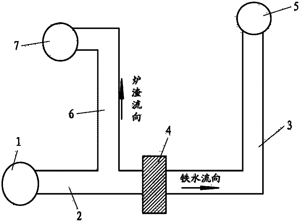
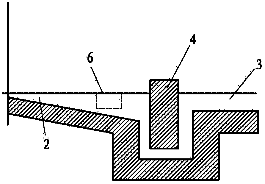

Image

  • Blast furnace slag-iron separation device, slag-iron separation method and discharged blast furnace slag-iron recovery method
  • Blast furnace slag-iron separation device, slag-iron separation method and discharged blast furnace slag-iron recovery method
  • Blast furnace slag-iron separation device, slag-iron separation method and discharged blast furnace slag-iron recovery method

Examples


Embodiment 1

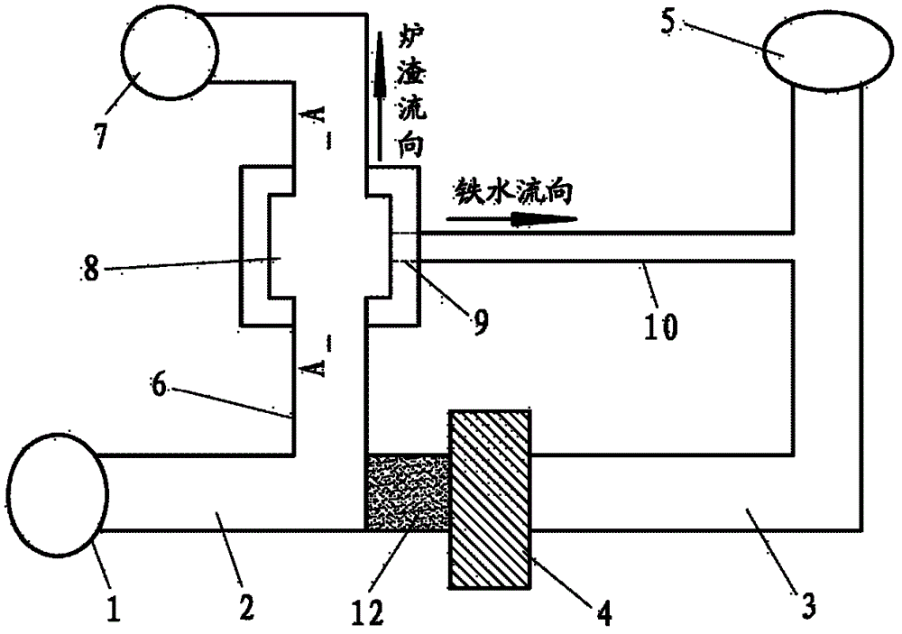
[0046] According to attached Figure 3B In the shown structure, the structural parts of sinking pool 8, small taphole 9, short vertical section 11 and molten iron branch ditch 10 are fabricated in the slag ditch by on-site casting. After the furnace is turned on to supply air and ignite, due to the high temperature of the furnace, the fluidity of molten iron and slag is poor. In order to prevent the effluent from flowing into the skimmer 4 and cause the skimmer 4 to become stuck and affect the normal separation of slag and iron in front of the furnace, use a The yellow sand forms a barrier before and within the skimmer 4 .

[0047] The first iron tapping after the blast furnace is opened. Before the blast furnace taphole 1 is opened for the first time, the small taphole 9 is blocked. After the blast furnace taphole 1 is opened, the effluent flows directly from the slag-iron ditch 2 into the slag ditch 6, with a slag output of 10 tons and no iron. Therefore, there is no need...

Embodiment 2

[0054] Due to the long-term slag containing more iron in a blast furnace, the iron loss of the blast furnace is relatively high. The slag ditch was modified to recover the molten iron in the slag. Since this blast furnace has a single tap hole, the tapping interval is very short, generally less than 30 minutes. In order to achieve continuous tapping, the Figure 3B The blast furnace slag-iron separation device with the structure shown, and the structural parts of the iron sinking pool 8, the small taphole 9, the short vertical section 11 and the molten iron branch ditch 10 are fabricated by the method of on-site casting. The slag iron ditch 2 and the skimmer 4 do not make any changes.

[0055] After the transformation, before opening the blast furnace taphole 1 for the first time, the small taphole 9 needs to be blocked. After the blast furnace taphole 1 is opened, the effluent passes through the slag skimmer 4 and is separated into slag containing a small amount of molten i...

Embodiment 3

[0059] A vanadium-titanium ore smelting blast furnace has a high iron loss due to the long-term slag containing a lot of iron, so the structure of the separation device was modified. Since this blast furnace has three taps, the tapping interval is longer. To prevent the solidification of molten iron in the short vertical section, a Figure 3A The blast furnace slag-iron separation device with the structure shown is to dig deep and wide the upstream section of the slag ditch 6 to form a sinking iron pool 8, and compact it with baking-free mud on the surface; Iron bent pipe (which can be made by bending the oxygen blowing pipe) to form a small taphole 9, and an inclined molten iron branch ditch 10 is temporarily set on the outside, and the molten iron branch ditch 10 is connected to the sinking iron pool through the small taphole 9 8 connected.

[0060] When tapping, after the blast furnace taphole 1 is opened, the effluent is separated into slag containing a small amount of m...


PUM


Abstract

The invention discloses a blast furnace slag-iron separation device, a slag-iron separation method and a discharged blast furnace slag-iron recovery method. The blast furnace slag-iron separation device comprises a slag-iron runner, a molten iron runner and a slag runner, wherein the slag-iron runner is connected with a tap hole of a blast furnace, the molten iron runner with a skimmer is used for connecting the slag-iron runner and an iron container, and the slag runner is used for connecting the slag-iron runner and the slag container. The separation device further comprises an iron settling tank, a small tap hole, a molten iron lateral runner and a stopper. The slag-iron separation method employs the blast furnace slag-iron separation device to separate effluent from the tap hole of the blast furnace so as to obtain slag and molten iron while the blast furnace skimmer is disabled. The discharged blast furnace slag-iron recovery method employs the blast furnace slag-iron separation device to recover the molten iron in the slag with rich iron.

Description

technical field [0001] The invention relates to the separation step of blast furnace slag and iron in the blast furnace production process, more specifically, relates to a blast furnace slag and iron separation device, a slag and iron separation method and a blast furnace lower slag and iron recovery method. Background technique [0002] Hot metal and slag are the main products produced by blast furnaces. During the blast furnace tapping process, iron slag (ie, slag and molten iron) is simultaneously discharged from the taphole. The skimmer in front of the furnace is a device used to separate slag and iron. Whether it can work normally directly determines whether the production of the blast furnace can continue. During periods such as blast furnace start-up and recovery of special furnace conditions (blast furnace hot junction, etc.), due to the poor fluidity and poor separation effect of the slag-iron mixed liquid, the slag and molten iron are directly separated by a slag ...

Claims


Application Information

Patent Timeline
Patent Type & Authority Patents(China)
IPC IPC(8): C21B7/14C21B3/06
CPCY02W30/50
Inventor 杨兵黄云
Owner PANGANG GRP XICHANG STEEL & VANADIUM CO LTD
Learn More