Energy dissipation method of sidewall aeration steps and outlet submerged flip bucket of inclined shaft type flood discharge tunnel

A technology for aeration sills and flood discharge tunnels, which is applied in water conservancy projects, marine engineering, coastline protection, etc., can solve problems such as landslides and environmental degradation, short-circuiting of high-voltage transformers, and damage to shore roads, etc. Energy dissipation rate, improve the effect of energy dissipation

Inactive Publication Date: 2012-08-01
SHANGHAI HONGBO PROJECT MANAGEMENT
View PDF6 Cites 9 Cited by
  • Summary
  • Abstract
  • Description
  • Claims
  • Application Information

AI Technical Summary

Problems solved by technology

This kind of high-speed water ejection will cause serious river bed erosion. At the same time, due to the aeration and diffusion of high-speed water in the air, as well as the impact of high-altitude landing on the river, the splash of tall waves will be mixed with the atmosphere again to form serious atomization. During the heavy rain, when some flood discharge tunnels discharge flood, the rainfall due to atomization can reach 1000mm / h, seriously destroying the ecological vegetation, causing landslides and environmental degradation
Due to the dust and sand carried by the atomization of the outlet deflection flow, it will also short-circuit the high-voltage transformer, resulting in power interruption, and at the same time destroying the shore road

Method used


Image

  • Energy dissipation method of sidewall aeration steps and outlet submerged flip bucket of inclined shaft type flood discharge tunnel
  • Energy dissipation method of sidewall aeration steps and outlet submerged flip bucket of inclined shaft type flood discharge tunnel
  • Energy dissipation method of sidewall aeration steps and outlet submerged flip bucket of inclined shaft type flood discharge tunnel

Examples


Embodiment 1

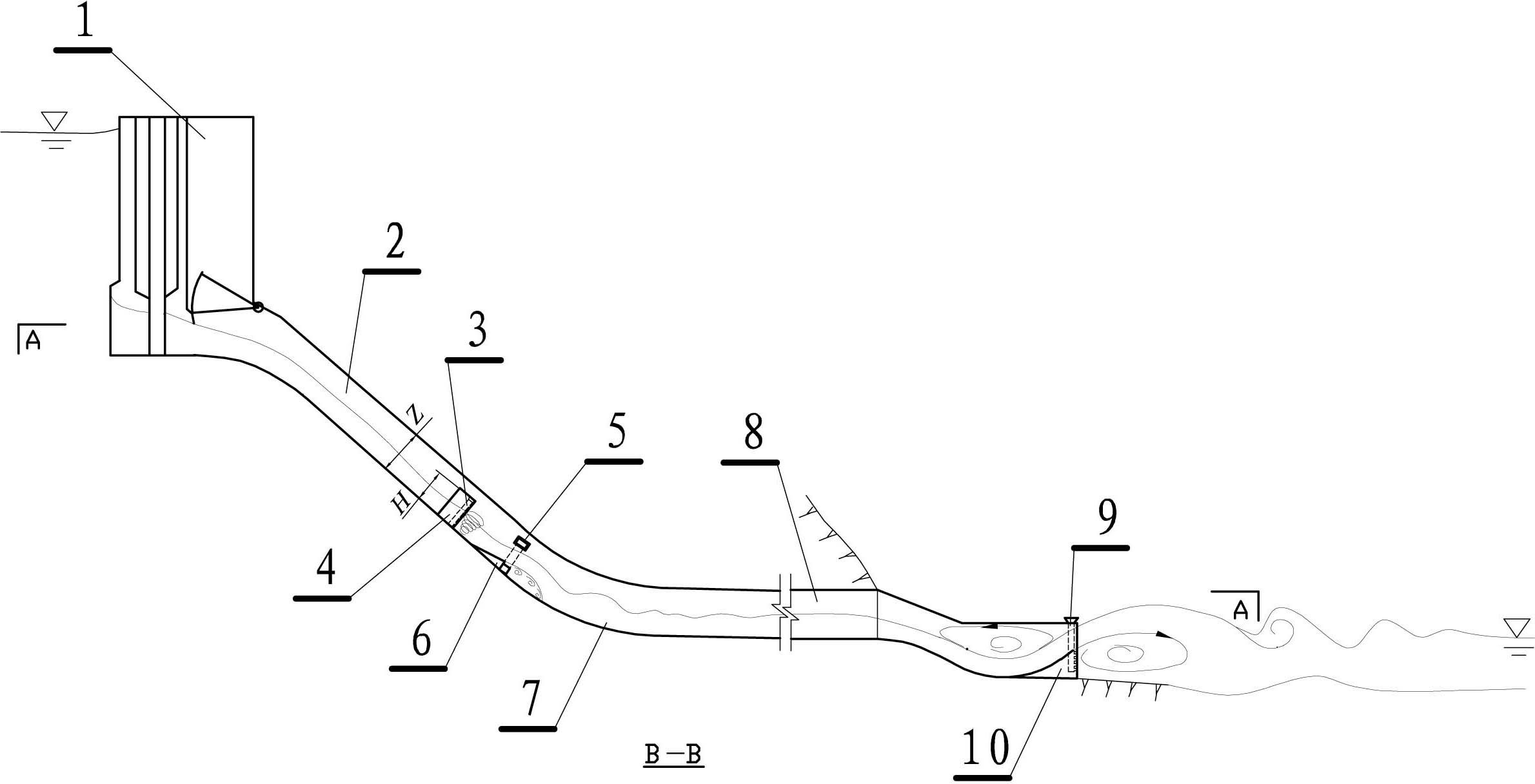
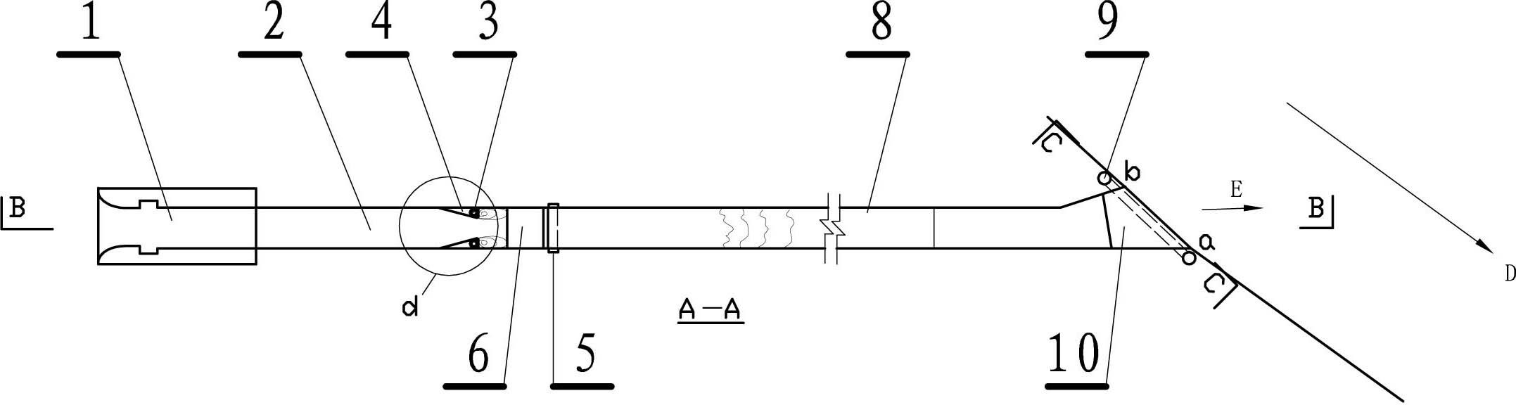
[0021] This embodiment is an energy dissipator for the side wall aeration sill and the outlet diving deflector sill of an inclined shaft type flood discharge tunnel, such as figure 1 , 2 shown. The inclined well type flood discharge tunnel described in this embodiment includes: a water inlet 1, the water inlet is connected to the inclined well 2, the inclined well is connected to the water outlet hole 8, and the reverse arc connecting the inclined well to the water outlet hole The bottom plate at the beginning of the section 7 is provided with a main aeration sill 6 with a vent pipe 5, and a pair of side aeration chambers with a vent pipe 3 are arranged opposite to each other on the two side walls of the upstream of the main aeration sill. Air barrier 4. The position of the outlet of the outlet hole is set below the flood water level of the river, the angle between the outlet of the outlet hole and the water flow of the river is less than 90 degrees and expands along the dir...

Embodiment 2

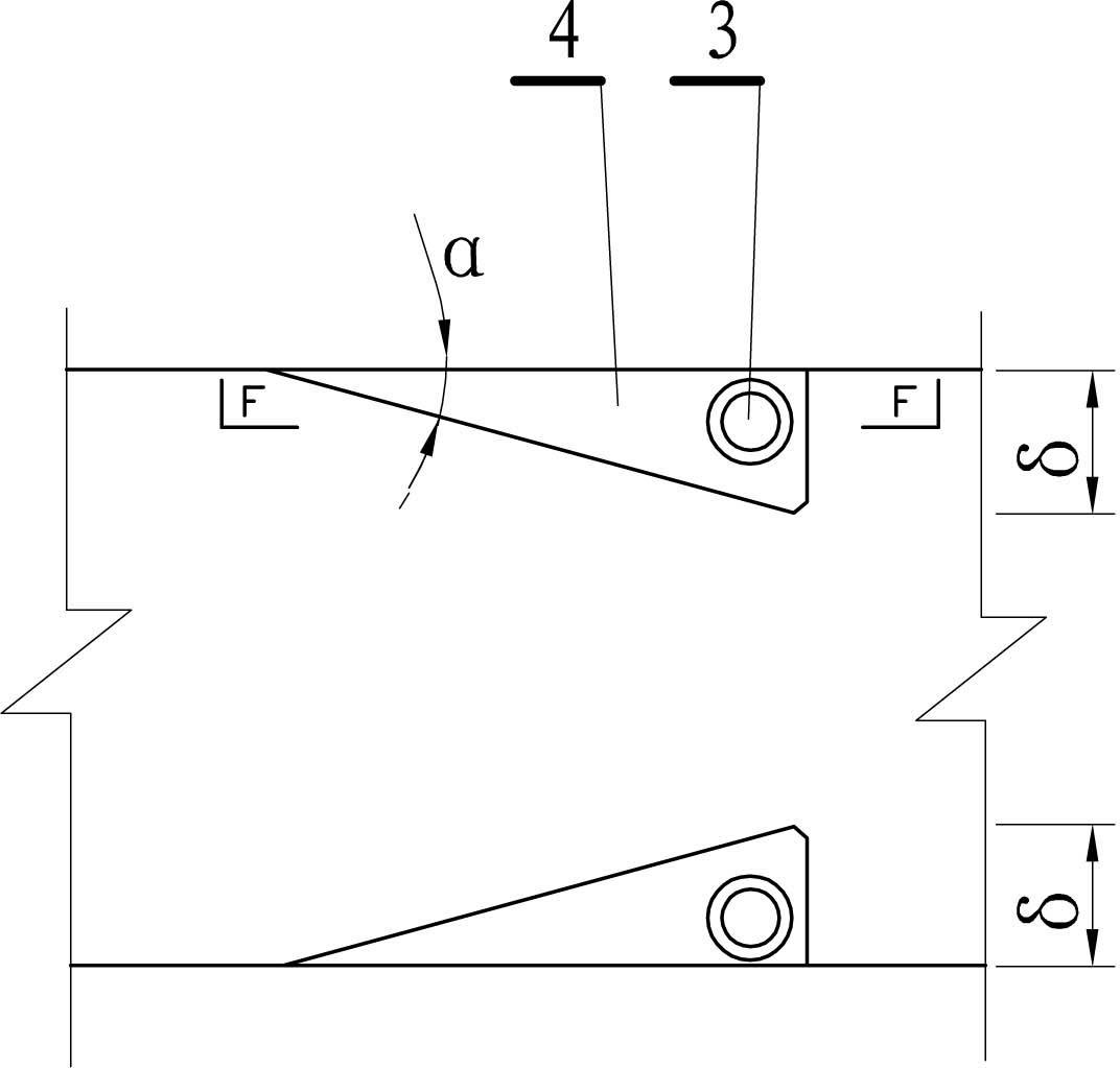
[0029] This embodiment is an improvement described in Embodiment 1, and it is a refinement of the side air-entrainment sill described in Embodiment 1, such as image 3 , 4 shown. The ventilation pipe of the side aeration sill described in this embodiment consists of a main pipe 301 and a branch pipe 302 connected to the main pipe. The air inlet of the main pipe is arranged on the top of the side aeration sill, and the air outlet of the branch pipe is arranged On the backside of the side aeration ridge. The protruding angle α of the side aeration sill is less than or equal to 15 degrees. The flow area between the two side aeration sills is not less than 0.65 times the cross-sectional area of ​​the inclined well.

[0030] The cross-sectional shape of the side aeration sill described in this embodiment is a triangular cross-section, and the height from the bottom plate H Should meet 0.7 Z H Z condition( Z - section height of the inclined shaft, see figure 1 ), H It shal...

Embodiment 3

[0032] This embodiment is an improvement of the above-mentioned embodiment, and it is a refinement of the above-mentioned embodiment about the diving sill, such as Figure 5 , 6 mentioned. The ventilation pipe of the diving sill described in this embodiment is connected along the back water surface of the diving sill, and the air inlet 901 of the ventilation pipe is arranged above the highest flood water level of the river channel, and is placed on the diving sill. A plurality of air outlets 902 are evenly arranged on the backside of the ridge.

[0033] The diving sill described in this embodiment is poured below the downstream design flood level, while the traditional sill is poured above the downstream checked flood level. The sill height of the diving sill described in the present embodiment is also changed along the flow direction of the river channel, from the low sill b straight line to the high sill a (see Figure 5 ), but the corresponding shooting angle β is smalle...


PUM


Abstract

The invention relates to an energy dissipation method of sidewall aeration steps and an outlet submerged flip bucket of an inclined shaft type flood discharge tunnel. The energy dissipation method adopts the structure that a water inlet is connected with an inclined shaft, the inclined shaft is connected with an effluent cave, a main aeration step with a vent pipe is arranged on the bottom plate of the starting position of the anti-arc segment, connected with the effluent cave, of the inclined shaft, and a pair of side aeration steps respectively provided with a vent pipe are oppositely arranged on two sidewalls at the upstream of the main aeration step; and the outlet of the effluent cave is located below the flood elevation of a watercourse, and the bottom plate at the outlet of the effluent cave is provided with a submerged flip bucket which is provided with a vent pipe and gradually uplifts along the river flow direction and the flood discharge flow direction. According to the invention, air is sucked by the side aeration steps by vortex negative pressure, so that the sidewalls are protected from cavitation erosion, and the flip bucket with the vent pipe at the outlet of the flood discharge tunnel is arranged below the flood elevation, so that the water flow in the watercourse generates turbulent shearing, the energy dissipation rate is improved, the scouring to the watercourse is alleviated, the damage to the flood discharge tunnel and the landslide of the mountain body at the outlet downstream are avoided, and the ecological environment is greatly improved.

Description

technical field [0001] The invention relates to a method for dissipating energy of the side wall aeration sill and the outlet diving sill of an inclined shaft type flood discharge tunnel, which is an energy dissipation method and facility for water conservancy projects, and is a flood discharge device for flood control and discharge of reservoirs. Energy dissipation methods and energy dissipation settings in holes. Background technique [0002] In the traditional inclined well type flood discharge tunnel, the flood water enters the anti-arc section through the inclined well from the water inlet, and then throws the water flow to the downstream Hanoi through the outlet sill of the flat tunnel. Under the action of high-speed water flow, the bottom plate at the end of the anti-arc section is very easy to cause serious damage due to cavitation. For example, the cavitation damage with a depth of 3 meters in the flood discharge tunnel of the Hoover Dam in the United States, the d...

Claims


Application Information

Patent Timeline
Patent Type & Authority Applications(China)
IPC IPC(8): E02B8/06
Inventor 董兴林杨开林李福田付辉郭新蕾王涛郭永鑫
Owner SHANGHAI HONGBO PROJECT MANAGEMENT
Why Eureka
Try Eureka