Polarization and birefringence measuring system

A measurement system and birefringence technology, applied in the field of polarization and birefringence measurement systems, can solve the problems affecting the performance of the 193nm exposure optical system, short wavelength, and difficulty in space and time for fast and accurate measurement, so as to suppress noise and improve measurement accuracy. , the effect of avoiding nonlinear errors

Active Publication Date: 2013-11-06
INST OF OPTICS & ELECTRONICS - CHINESE ACAD OF SCI
View PDF9 Cites 0 Cited by
  • Summary
  • Abstract
  • Description
  • Claims
  • Application Information

AI Technical Summary

Problems solved by technology

After simulation analysis, because the birefringence effect of the material may cause 4-6nm wave aberration changes, which will seriously affect the performance of the 193nm exposure optical system, it is necessary to accurately measure the polarization effect and birefringence distribution of the material. However, the polarization effect of the material and fast and precise measurements of birefringence patterns and distributions are difficult in space and time, but are necessary for the development of 193nm ArF immersion lithography machines
[0005] Since the reliability of wave aberration quality is closely related to precision optical imaging systems such as lithography exposure systems with a line width of 90 nm, for exposure systems with a line width of 22 nm or even 16 nm, the numerical aperture of the lithography projection objective lens is greater than 1, in order to meet The requirement of high resolution, the wavelength is very short, such as 193 nanometers now, with the shortening of the wavelength, the degree of scattering is quite serious, the stability of the measurement system and the repeatability of the measurement results are a huge challenge we face

Method used


Image

  • Polarization and birefringence measuring system
  • Polarization and birefringence measuring system
  • Polarization and birefringence measuring system

Examples


Embodiment Construction

[0018] In order to better illustrate the purpose and advantages of the present invention, the present invention will be further described below in conjunction with the accompanying drawings.

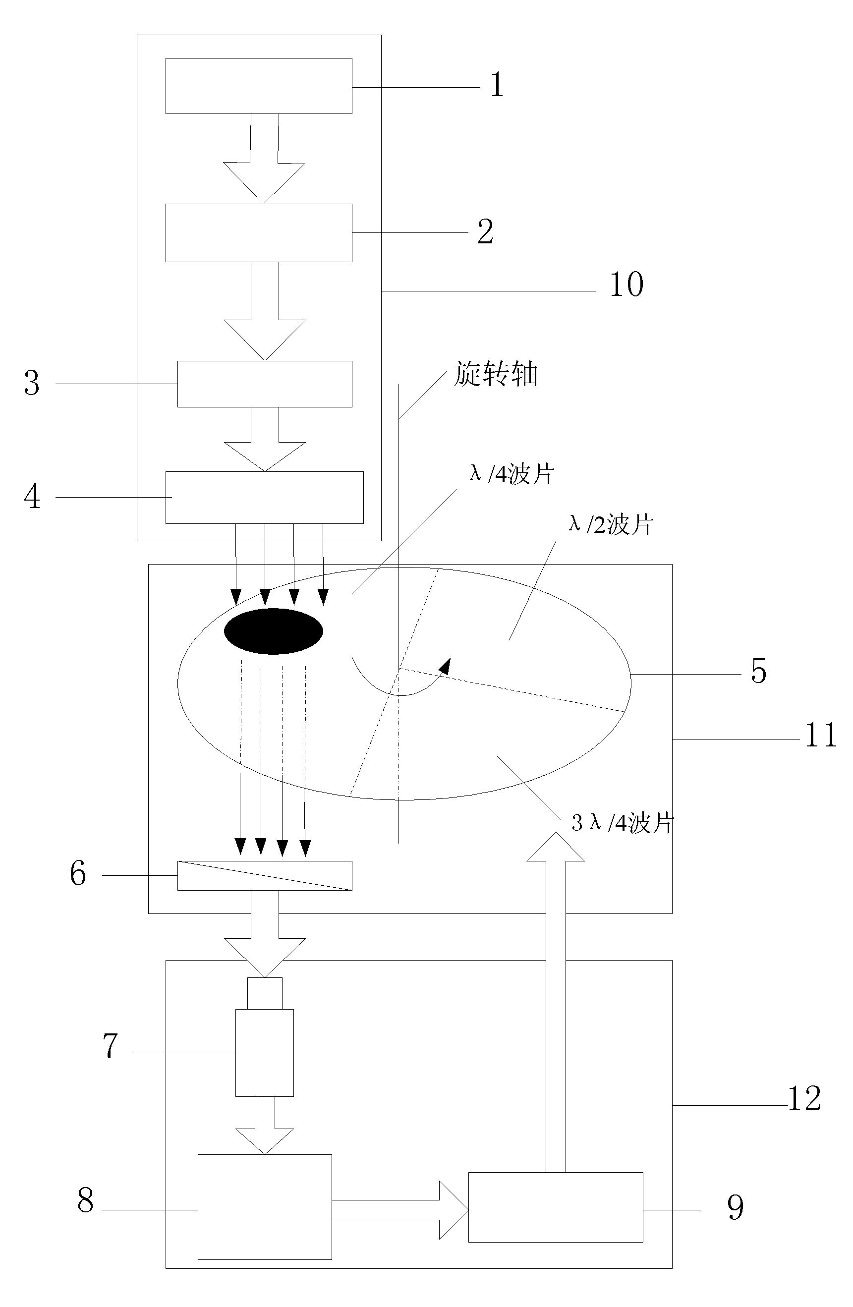
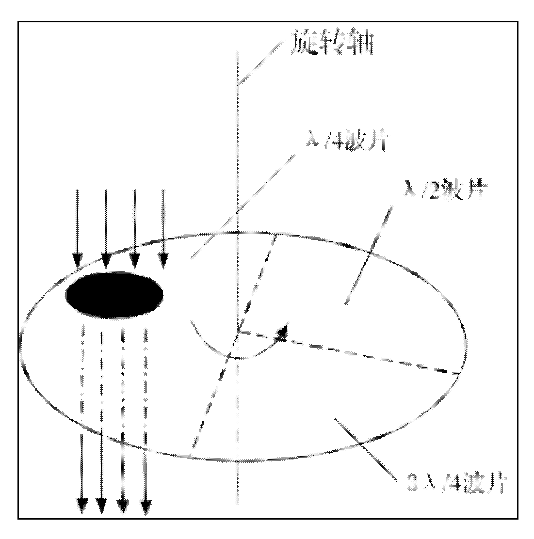
[0019] figure 1 It is a schematic diagram of the measurement principle of a polarization and birefringence measurement system, including a light source module 10, an optical signal modulation module 11, and a data acquisition and processing module 12. The light source module 10 includes a light source 1, a collimating beam expander system 2, and a polarizer 3 , the sample to be tested 4; the optical signal modulation module 11 includes a multi-stage phase difference coaxial wave plate 5 and a polarizer 6; the data acquisition and processing module 12 includes a light intensity detector 7, a computer 8 and a stepping motor 9. Such as figure 1 As shown, the light source 1 is an ArF laser with a wavelength of 193.368nm. The light emitted by the ArF laser passes through the collimator beam ...


PUM

PropertyMeasurementUnit
wavelengthaaaaaaaaaa

Abstract

The invention provides a polarization and birefringence measuring system in which measuring accuracy of polarization and stress birefringence is increased by using a multi-wave plate combination. The measuring system comprises a light source module, a light signal modulation module and a data collecting and processing module, wherein the light source module comprises a light source, a collimation and expansion system and a polarizer; the light signal modulation module comprises a multilevel phase difference coaxial wave plate, an analyzer, a stepping motor driving device and a stepping motor; and the data collecting and processing module comprises an image capture card, an luminous intensity detector and a computer. According to the polarization and birefringence measuring system, influences of changes of environments and measurement conditions such as air movement, temperature variation and uncertain vibration modes are effectively avoided; more than one independent phase modulation element is used for suppressing noises and averaging main error sources; and three wave plates are used for measuring the polarization and the birefringence, so that non-linear errors caused by non-linear influence of the system are effectively avoided, and the measuring accuracy is greatly improved.

Description

technical field [0001] The invention belongs to the technical field of modern optical testing, in particular to a polarization and birefringence measurement system, which can accurately measure the distribution of polarization and birefringence. Background technique [0002] When the NA of the lithography projection objective lens is greater than 0.8, the polarization characteristics of the beam will seriously affect the imaging quality, especially the p-polarization will reduce the imaging contrast and affect the system resolution. In addition, the point spread function of polarized light is asymmetric, and the light intensity distribution spreads along the polarization direction. For line graphics, when the polarization direction is not parallel to the line, the light intensity transmittance is higher, which is conducive to imaging. Therefore, according to the mask pattern, the resolution and imaging quality of the system can be further improved by using the corresponding...

Claims


Application Information

Patent Timeline
Patent Type & Authority Patents(China)
IPC IPC(8): G01N21/23
Inventor 范真节林妩媚邢廷文刘学峰
Owner INST OF OPTICS & ELECTRONICS - CHINESE ACAD OF SCI
Why Eureka
Try Eureka