Maskless exposure system and exposure method thereof

An exposure system, maskless technology, applied in the field of semiconductor manufacturing, to achieve the effect of reducing costs

Inactive Publication Date: 2014-03-12
HANGZHOU SILAN AZURE
View PDF5 Cites 0 Cited by
  • Summary
  • Abstract
  • Description
  • Claims
  • Application Information

AI Technical Summary

Problems solved by technology

X-ray exposure is still in the experimental development stage and has not yet been used for mass production

Method used


Image

  • Maskless exposure system and exposure method thereof
  • Maskless exposure system and exposure method thereof
  • Maskless exposure system and exposure method thereof

Examples


Embodiment Construction

[0037] In order to make the purpose, technical solution and advantages of the present invention more clear, the following will be further described in detail in conjunction with the accompanying drawings.

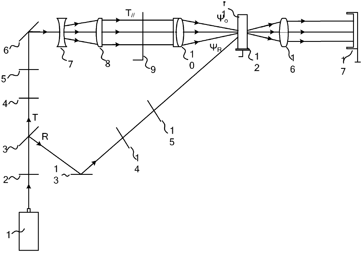
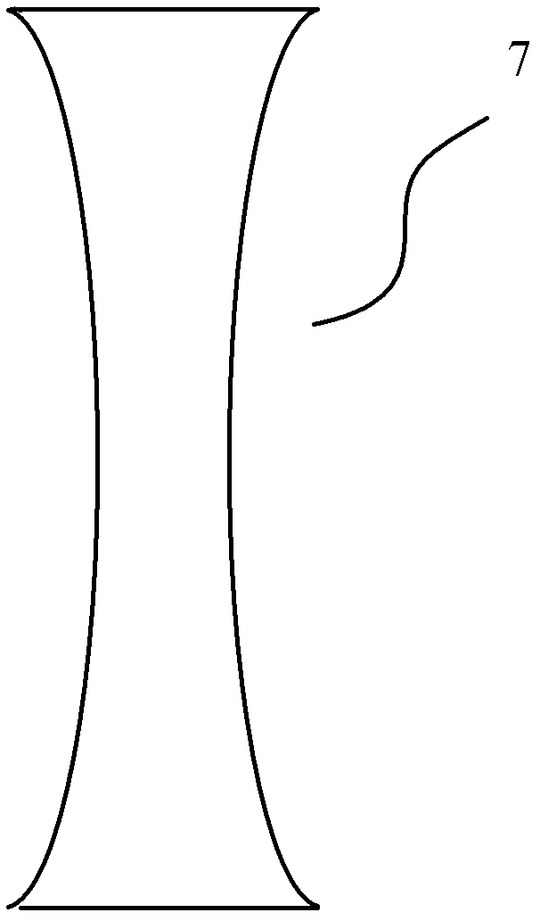
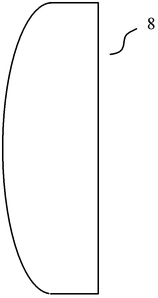
[0038] figure 1 It is a schematic diagram of the overall structure of a maskless exposure system in an embodiment of the present invention. The maskless exposure system includes: a laser light source 1, a half-wave plate 2, a beam splitter 3, a first light intensity attenuator 4, a first electric shutter 5, a first reflector 6, a beam expander 7, a quasi- Straight mirror 8, mask plate support frame 9, Fourier transform lens 10, photorefractive crystal 11, fixed turntable 12, second mirror 13, second light intensity attenuator 14, second electric shutter 15, imaging lens 16 and Wafer support frame 17.

[0039] The light emitted by the laser light source 1 reaches the beam splitter 3 after passing through the half-wave plate 2, and is divided into a transmitted beam T and a...


PUM

PropertyMeasurementUnit
diameteraaaaaaaaaa
diameteraaaaaaaaaa
diameteraaaaaaaaaa

Abstract

The invention provides a maskless exposure system and an exposure method thereof. The maskless exposure system comprises a laser light source, a half-wave plate, a beam splitter mirror, a first light intensity attenuator, a first electric shutter, a first reflecting mirror, a beam expanding mirror, a collimating mirror, a mask support plate, a Fourier transform lens, a photorefractive crystal, a second reflecting mirror, a second light intensity attenuator, a second electric shutter, an imaging lens and a wafer support frame. Due to the adoption of the maskless exposure system provided by the invention, the quantity of masks can be reduced greatly, and cost of the masks caused by the use of multiple sets of masks is lowered.

Description

technical field [0001] The invention belongs to the field of semiconductor manufacturing, and in particular relates to a maskless exposure system and an exposure method thereof. Background technique [0002] Photolithography is one of the most critical technologies in the semiconductor manufacturing industry. Its exposure technology can be divided into traditional optical exposure, electron beam exposure, ion beam exposure and X-ray exposure. [0003] Contact exposure in traditional optical exposure technology can obtain higher resolution, but the result of repeated contact between the mask and the wafer is to generate defects on the mask, which will be copied repeatedly to the wafer, resulting in product yield drops. Although the proximity exposure avoids the defects caused by the contact exposure, the sharp decrease in resolution is caused by the increase of the gap. Projection exposure uses the principle of optical projection imaging to project the mask onto the wafer f...

Claims


Application Information

Patent Timeline
Patent Type & Authority Patents(China)
IPC IPC(8): G03F7/20G02B27/10
Inventor 丁海生李东昇马新刚江忠永张昊翔
Owner HANGZHOU SILAN AZURE
Why Eureka
Try Eureka