Self-aligning packaging structure for micro-electromechanical system (MEMS) device and manufacture method thereof

A packaging structure and self-alignment technology, which is applied in manufacturing tools, microstructure technology, electric solid-state devices, etc., can solve the problems of bonding strength, poor sealing reliability, limited application range, high process consistency and uniformity, etc. problem, to achieve the effect of improving error tolerance, reducing equipment cost, and enhancing mechanical fastness

Active Publication Date: 2012-08-08
中科芯未来微电子科技成都有限公司
View PDF9 Cites 13 Cited by
  • Summary
  • Abstract
  • Description
  • Claims
  • Application Information

AI Technical Summary

Problems solved by technology

In 2002, Vladimir I. Vaganov et al. of the United States proposed a series of bonding area geometries for wafer bonding, but the content only involved the feasibility of a variety of wafer bonding area geometries, and did not discuss how to combine them with Combination of MEMS structure and packaging; In 2005, Chen Jing of Peking University and others proposed a high-precision packaging method based on MEMS, but the process required the use of additional micro-fixtures and did not propose the feasibility of using this method in wafer-level packaging ; In 2006, Sang Hwui Lee et al. proposed and manufactured an alignment mark structure with complementary slopes to achieve high-precision wafer alignment, but this structure has only been used in alignment marks, and is based on benzene Using cyclobutene as the intermediate bonding layer cannot achieve high-reliability hermetic packaging or even vacuum packaging of the MEMS structure. In addition, the alignment mark structure requires additional deposition materials, which has high requirements for process consistency and uniformity; In 2011, Kuan-Neng Chen and others also proposed a precision wafer bonding method using a slope structure, but this solution is limited to copper-copper bump bonding, and does not involve its feasibility in MEMS packaging; In the past period of time, there are many achievements of self-aligned packaging technology based on reflow soldering, which can meet the requirements of high-precision packaging to a certain extent
Among them, adhesive bonding requires the lowest bonding temperature, but its bonding strength, airtightness, and reliability are the worst among the four methods, and it is suitable for packaging occasions that do not require high reliability and airtightness; According to different bonding materials, crystal bonding needs to provide different bonding temperatures, but it is relatively higher than adhesive bonding, and the resulting bonding strength and sealing performance are better, so this technology has great potential in MEMS packaging. Very wide range of applications; both anodic bonding and silicon fusion technologies can achieve better packaging results, but the high requirements of these two technologies on the bonding surface limit their application range

Method used


Image

  • Self-aligning packaging structure for micro-electromechanical system (MEMS) device and manufacture method thereof
  • Self-aligning packaging structure for micro-electromechanical system (MEMS) device and manufacture method thereof
  • Self-aligning packaging structure for micro-electromechanical system (MEMS) device and manufacture method thereof

Examples


Embodiment Construction

[0050] The present invention will be further described below in conjunction with specific drawings and embodiments.

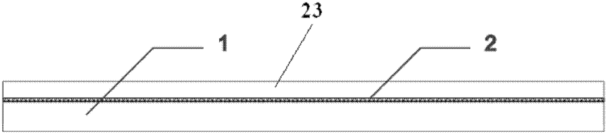
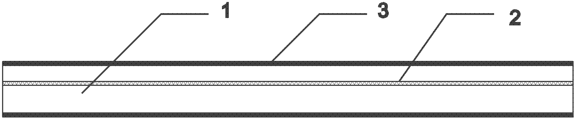
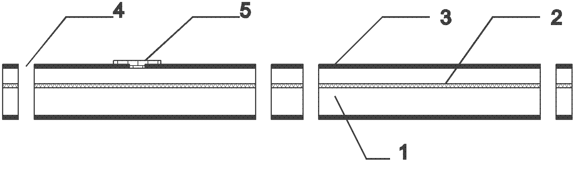
[0051] like Figure 11 Shown: is the chip-level self-aligned packaging structure obtained in the present invention; the chip-level self-aligned packaging structure of the present invention includes a cover plate 26 and a carrier substrate 27 directly below the cover plate 26; the carrier substrate 27 A MEMS structure 5 is provided on the top, and the cover plate 26 is concavely provided with an accommodating groove 9 for accommodating the MEMS structure 5. The MEMS structure 5 extends into the accommodating groove 9, and the bottom of the accommodating groove 9 is provided with a getter 10; The outer side of the plate 26 corresponding to the notch of the receiving groove 9 is provided with a cover plate bonding positioning projection 29, and the cover plate 26 is provided with a cover plate bonding layer 28 on the side surface corresponding to the cover plate b...


PUM

PropertyMeasurementUnit
angleaaaaaaaaaa
angleaaaaaaaaaa
thicknessaaaaaaaaaa

Abstract

The invention relates to self-aligning packaging structure for a micro-electromechanical system (MEMS) device and a manufacture method thereof. The self-aligning packaging structure for the MEMS device comprises a cover plate and a load bearing substrate. An MEMS structure is arranged on the load bearing substrate, an accommodating groove is arranged in the recessed cover plate, the MEMS structure penetrates into the accommodating groove, and a getter is arranged at the bottom of the accommodating groove. The outer side of the cover plate corresponding to a groove opening of the accommodating groove is provided with a cover plate bonding positioning protrusion, and the cover plate is provided with a cover plate bonding layer. A substrate bonding positioning protrusion is arranged on the load bearing substrate, a bonding positioning groove is arranged between the substrate bonding positioning protrusion and the MEMS structure, and a substrate bonding layer is arranged on the surface of the load bearing substrate. The cover plate bonding positioning protrusion extends into the bonding positioning groove and then corresponds to and is matched with the bonding positioning groove so as to achieve self aligning, the cover plate bonding layer is in corresponding contact with the substrate bonding layer, and the cover plate and the load bearing substrate are integrally connected after the cover plate bonding layer and the substrate bonding layer are bonded. The self-aligning packaging structure for the MEMS device is simple and compact in structure and can meet the high-precision packaging requirement of the MEMS, increase the area of the bonding region and improve the reliability and leakproofness of package.

Description

technical field [0001] The invention relates to a self-aligned packaging structure and a manufacturing method thereof, in particular to a self-aligned packaging structure for MEMS devices and a manufacturing method thereof, belonging to the technical field of MEMS packaging. Background technique [0002] According to reports, depending on the product, the packaging cost of MEMS accounts for 40% to 80% of the entire MEMS product; at the same time, the performance and reliability of MEMS devices are inextricably linked to their packaging form and packaging technology. Due to the particularity of the structure of MEMS devices, its packaging is much more complicated than traditional integrated circuit packaging: firstly, it is necessary to consider the same important electrical and mechanical components in MEMS devices; secondly, some MEMS devices need to be in contact with the external environment or with the outside world. The environment is completely isolated; finally, as th...

Claims


Application Information

Patent Timeline
Patent Type & Authority Applications(China)
IPC IPC(8): B81B7/00B81C3/00
Inventor 秦毅恒明安杰
Owner 中科芯未来微电子科技成都有限公司
Why Eureka
Try Eureka