
Composite precipitation tank with function of sludge carbon source transformation

A technology of composite sedimentation and sludge carbon, applied in the field of composite sedimentation tanks, can solve the problems of staying in the research and small test stage, and there is no report on the development and development of complete sets of equipment, so as to improve the efficiency of sludge hydrolysis, reduce investment costs, and reduce land use area effect

Inactive Publication Date: 2012-08-08
TONGJI UNIV
View PDF7 Cites 7 Cited by
  • Summary
  • Abstract
  • Description
  • Claims
  • Application Information

AI Technical Summary

Problems solved by technology

[0005] According to the literature search of the existing technology, it is found that domestic research on the development of carbon sources by hydrolysis of sludge in sedimentation tanks only stays in the research and small test stage, and there is no report on the development and development of related complete sets of equipment.

Method used


Image

  • Composite precipitation tank with function of sludge carbon source transformation
  • Composite precipitation tank with function of sludge carbon source transformation
  • Composite precipitation tank with function of sludge carbon source transformation

Examples


Embodiment Construction

[0037] Embodiment of the present invention is described in detail below in conjunction with accompanying drawing: present embodiment implements under the premise of technical scheme of the present invention, has provided detailed mode and work process, but protection scope of the present invention is not limited to following embodiment .

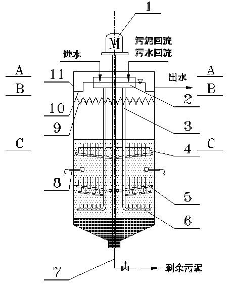
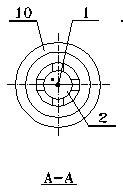
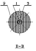
[0038] Such as figure 1 As shown, the composite sedimentation tank with the conversion function of sludge carbon source mainly includes: 1. Central frequency conversion transmission device; 2. Sludge water mixer; 3. Diversion pipe; Crushing device; 6. Slurry separator; 7. Sludge discharge device; 8. Ultrasonic generator; 9. Solid-liquid separator; 10. Rectification outlet weir. The whole equipment is divided into five parts according to different functions: 1. Carbon source conversion area - sludge is decomposed and converted into high-quality carbon source in this area; 2. Anaerobic / anoxic area - nitrate-containing sewage utilizes carbon s...


PUM


Abstract

The present invention relates to a composite precipitation tank with a function of sludge carbon source transformation. The composite precipitation tank comprises a center frequency conversion transmission, a slush mixer, a honeycomb duct, sludge crushing devices, slush distributor, a mud discharging device, an ultrasonic generator, a solid-liquid separator and a rectification water outlet weir. The center frequency conversion transmission is inserted into the tank body from top to bottom. The slush mixer is located in inner upper part of the tank; and periphery of the slush mixer is rectification water outlet weir. The solid-liquid separator is located in a middle and upper part in the tank. An upper sludge crushing device is located in a central part in the tank; and a lower sludge crushing device is located in a lower part in the tank. The ultrasonic generator is arranged between the upper and lower sludge crushing devices. The mud discharging device is located at the bottom of the tank. The slush distributor is arranged between the lower sludge crushing device and the mud discharging device. The honeycomb duct is L-shaped and extends into the tank; one end of the honeycomb duct is positioned below the slush mixer, and the other end is located below the lower sludge crushing device and connected with the slush distributor. The invention has the advantages of simple process, land saving, convenient management, greatly reduced cost of the operation and stable water outlet effect, and can be widely used in sewage treatment plant for nitrogen and phosphorus removal standard upgrade reconstruction, as well as in nitrogen removal treatment on low carbon source polluted water.

Description

technical field [0001] The invention relates to equipment in the technical field of sewage treatment, in particular to a composite sedimentation tank with the function of sludge carbon source conversion. Background technique [0002] During my country's "Eleventh Five-Year Plan" period, the national urban sewage treatment capacity continued to grow rapidly, and the actual amount of sewage treated and the total amount of pollutants reduced increased significantly. However, due to the construction of the pipeline network, especially the inadequate reconstruction of the rainwater and sewage diversion system, coupled with the prominent problems of mixed rainwater and sewage and leakage of the pipeline network, the concentration of pollutants in the influent of the sewage treatment plant is relatively low, which hinders the effect of nitrogen and phosphorus removal. It has a great impact and seriously affects the removal efficiency of pollutants. At present, among the sewage tre...

Claims


Application Information

Patent Timeline
IPC IPC(8): C02F3/28C02F11/04C02F11/12C02F1/52
Inventor 张杰杨殿海徐伟张浩
Owner TONGJI UNIV
Learn More