Wind driven generator for ship

A technology for wind power generation devices and ships, which is applied in the direction of wind power generator components, wind power generation, wind power engines, etc. It can solve problems such as no solution, difficult installation and maintenance, and large resistance, so as to enhance reliability and vitality, and occupy Small space, easy to achieve effect

Inactive Publication Date: 2012-08-15
HARBIN ENG UNIV
View PDF8 Cites 6 Cited by
  • Summary
  • Abstract
  • Description
  • Claims
  • Application Information

AI Technical Summary

Problems solved by technology

The patent authorization announcement number is CN1887647A, and the name is "ship wind energy utilization device", which provides a wind energy utilization device based on the principle of an umbrella. The rotating shaft of the generator is inside a hollow cylinder, and the top of the hollow cylinder is controlled by a telescopic rod. The expansion and closure of the wind blades, but this device has a complex structure, is not easy to install and maintain, and is limited by the center of gravity of the ship, so it is difficult to be widely used on ships
The patent authorization announcement number is CN2031843U, and the title is "Cylindrical inner leaf vertical axis wind turbine wind wheel structure" provides an improved cylindrical vertical axis wind turbine wind wheel structure, which is simple in structure and can be used in a wide range. However, the patent does not specifically point out the combination of the wind rotor and the generator shaft, nor does it point out the fixed position and installation of the wind rotor and generator
The patent authorization announcement number is CN2135660Y, and the name is "Vertical Axis Tower Wind Power Machine", which provides a vertical axis tower structure wind energy utilization device composed of multiple groups of wind wheels connected in series. This device has a large installation height, strong starting wind force, The structure is simple and the overall performance is good, but in modern ships, the fan can only be used as an auxiliary machine. In the case where it is not suitable to use wind power generation devices, no effective solution is proposed here, and it takes up a lot of space on the ship, so it is difficult to implemented in modern ships
The patent authorization announcement number is CN201517467U, and the name is "sail-type vertical axis wind-powered engine", which provides a wind-driven engine that can expand the wind-receiving area of ​​the blade from the width and length, and can fully utilize the wind energy in the downwind area. , but this device cannot realize the collection of propeller blades, and the resistance it receives is relatively large during ship navigation, and it is difficult to be widely used

Method used


Image

  • Wind driven generator for ship
  • Wind driven generator for ship
  • Wind driven generator for ship

Examples


Embodiment approach 1

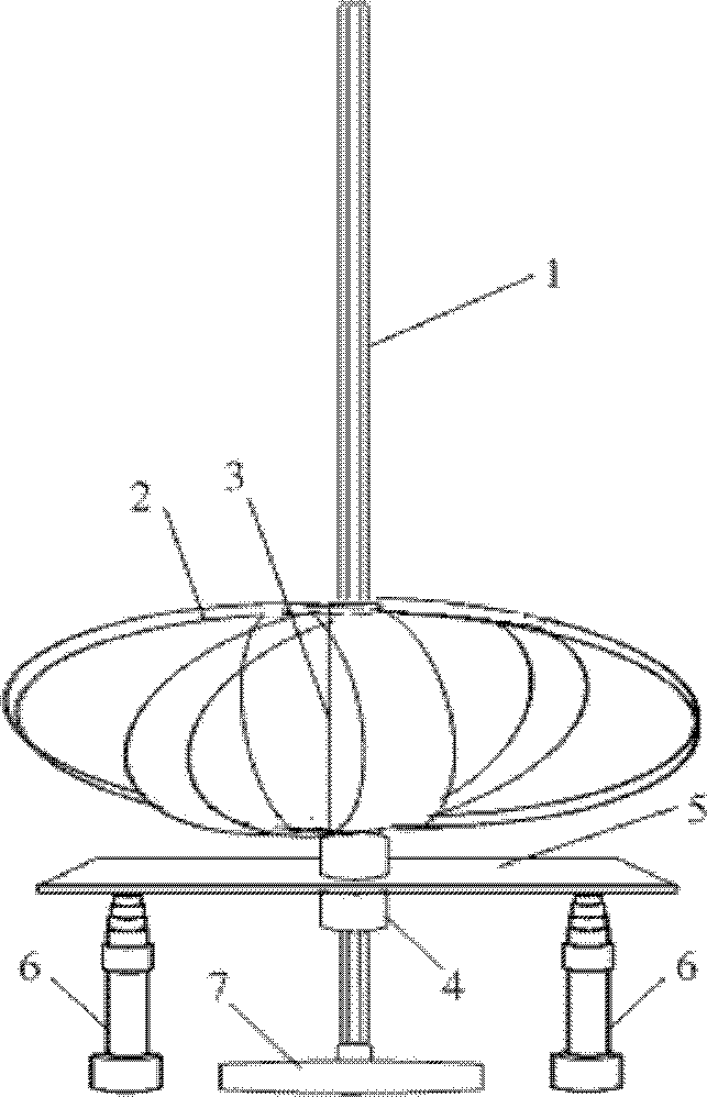
[0020] Implementation Mode 1: see figure 1 , this design is mainly aimed at wind turbines with high power and heavy weight. The two lifting rods 6 and the permanent magnet generator 7 can be fixed on the deck of the ship. The lifting height of the lifting rod 6 is 8-10 meters. Lifting rod or electric lifting rod, the lifting rod 6 is welded with the steel pallet 5, and the supporting pallet 5 is lifted up and down. The Darrieux wind turbine 2 and the steel cylindrical hexahedral hollow sleeve 3 are welded together, and then sleeved on the steel hexahedron hollow sleeve. On the major axis 1, the length of the hexahedral hollow major axis 1 is 8-10 meters. When the Darrieus wind turbine 2 rotates, it can drive the steel hexahedron hollow major axis 1 to rotate. The bottom end of the Darrieus wind turbine 2 is connected to the The inner ring of the steel bearing 4 is welded together, and the outer ring of the bearing 4 and the tray 5 are welded together. In this way, according ...

Embodiment approach 2

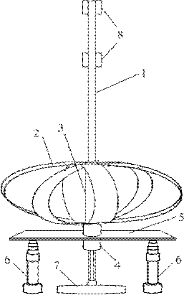
[0021] Implementation mode two: see figure 2 , this design scheme is mainly aimed at heavy generators. The two lifting rods 6 and the permanent magnet generator 7 can be fixed on the deck of the ship. The lifting height of the lifting rod 6 is 8-10 meters. Lifting rod or electric lifting rod, the lifting rod 6 is welded with the steel tray 5, the support tray 5 is lifted, the rotating shaft of the permanent magnet generator 7 is connected with the long axis 1 of the steel hollow cylinder, and the length of the long axis 1 of the hollow cylinder is 8-10 m, on the long axis 1 of the hollow cylinder, the steel card body 8 is welded according to the length of the sleeve 3, the two ends of the steel sleeve 3 are engraved with the card slot corresponding to the card body 8, and the card body 8 and the card slot are guaranteed Ensure that the Darrieus wind turbine 2 can rotate normally to drive the permanent magnet generator 7 to generate electricity, and the middle part of the sle...

Embodiment approach 3

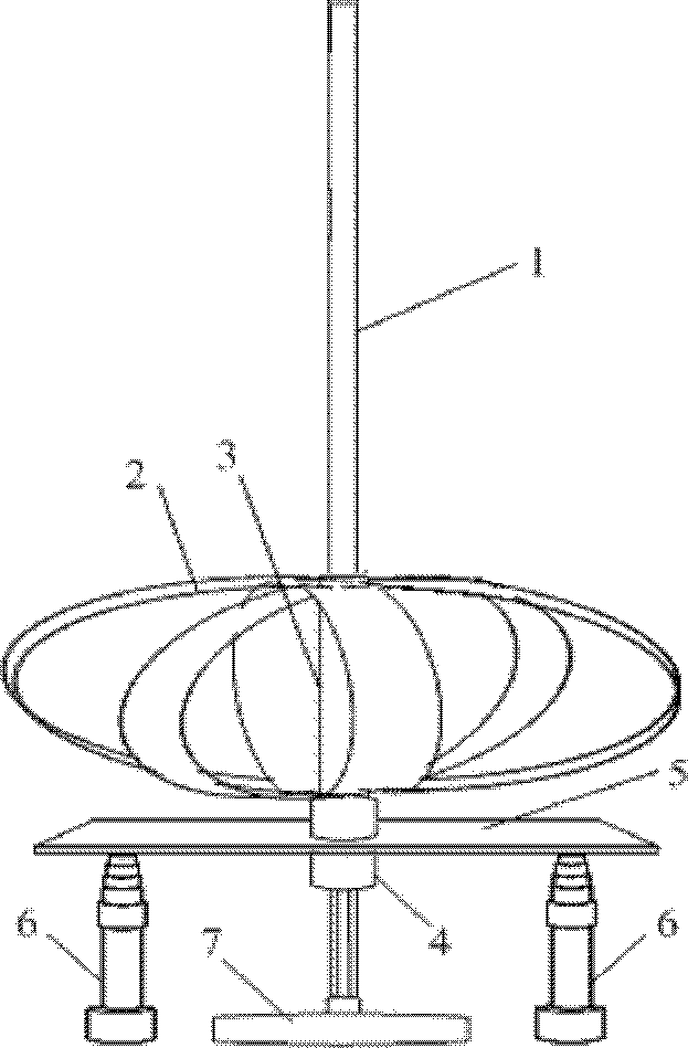
[0022] Implementation mode three: see image 3 , this design scheme is basically the same as scheme two, mainly aimed at heavy generators, two elevating poles 6 and permanent magnet generator 7 can be fixed on the ship deck, and the lifting height of elevating pole 6 is 8-10 meters, Each section of the lifting rod 6 adopts synchronous rising, and the rising speed is fast. According to the requirements, a manual lifting rod or an electric lifting rod can be selected. The lifting rod 6 is welded to the steel tray 5, and the lifting rod 6 supports the lifting of the pallet 5. The rotating shaft is connected with the steel hollow cylinder long axis 1 with two symmetrical long grooves engraved on the outside. The cross-sectional view of the hollow cylinder long axis 1 viewed from top to bottom is as follows: Figure 5 As shown, the length of the long axis 1 of the hollow cylinder is 8-10 meters, the steel hollow sleeve 3 is connected with the Darrieus type wind turbine 2, and two s...


PUM


Abstract

The invention aims at providing a wind driven generator for a ship. The wind driven generator comprises a wind turbine, a permanent magnet generator and a lifting rod, wherein the wind turbine is connected with a rotating shaft of the permanent magnet generator, so that a vertical wind generating set is formed, and the lifting rod supports the wind turbine and the permanent magnet generator and can be lifted up and down. The wind driven generator is simple and easy to realize on the ship, the offshore wind energy can be adequately used, so that the pollution to the sea when the ship uses the conventional energy can be reduced. In the case that a power device of the ship is broken, even the spare generating set, the emergency standby power, the storage battery and the like can not run normally, the lifting rod can be manually operated, so that the wind turbine or the small-size wind generating set can be lifted up to a preset height for generating electricity. Therefore, in the emergency case that the ship is lack of power, the electricity can be generated by the wind driven generator on the ship, so that that the influence to the normal work of a ship power system and an emergencyelectric equipment can be avoided, and the reliability and the life force of the ship power system can be enhanced.

Description

technical field [0001] The invention relates to a wind energy generating device in the field of clean energy. Background technique [0002] At present, the global petrochemical energy is gradually decreasing. As a non-polluting and infinitely renewable resource, wind energy is especially abundant on the sea surface. Using offshore wind energy to generate electricity on ships can effectively save traditional energy for ship power plants. consume. However, there are many factors affecting the application of wind power generation devices on ships, and it is difficult to popularize the application of wind power generation. The patent authorization announcement number is CN201778958U, and the title is "ship-borne liftable wind power generator tower", which provides a kind of ship-borne liftable wind power generator tower. The tower can be installed on various ships and is convenient for installation, disassembly, storage and transportation, but the device is not suitable for la...

Claims


Application Information

Patent Timeline
Patent Type & Authority Applications(China)
IPC IPC(8): F03D9/00F03D11/00B63H13/00F03D9/25F03D9/32F03D13/20
CPCY02E10/72Y02E10/728Y02E10/74Y02T70/5236
Inventor 程鹏李纪辉张敬南兰海田凯张强刘宏达李峰岩王庚秦鹏
Owner HARBIN ENG UNIV
Why Eureka
Try Eureka