Power supply device of current transformer

A technology of current transformers and power supply devices, applied in circuit devices, emergency protection circuit devices for limiting overcurrent/overvoltage, emergency protection circuit devices, etc., to reduce costs, improve conversion efficiency, and ensure reliability.

Active Publication Date: 2012-08-15
深圳市深泰明科技有限公司
View PDF7 Cites 25 Cited by
  • Summary
  • Abstract
  • Description
  • Claims
  • Application Information

AI Technical Summary

Problems solved by technology

[0026] In order to overcome the deficiencies of the prior art, the object of the present invention is to solve the problems existing in the existing CT power-taking t

Method used


Image

  • Power supply device of current transformer
  • Power supply device of current transformer
  • Power supply device of current transformer

Examples


Embodiment Construction

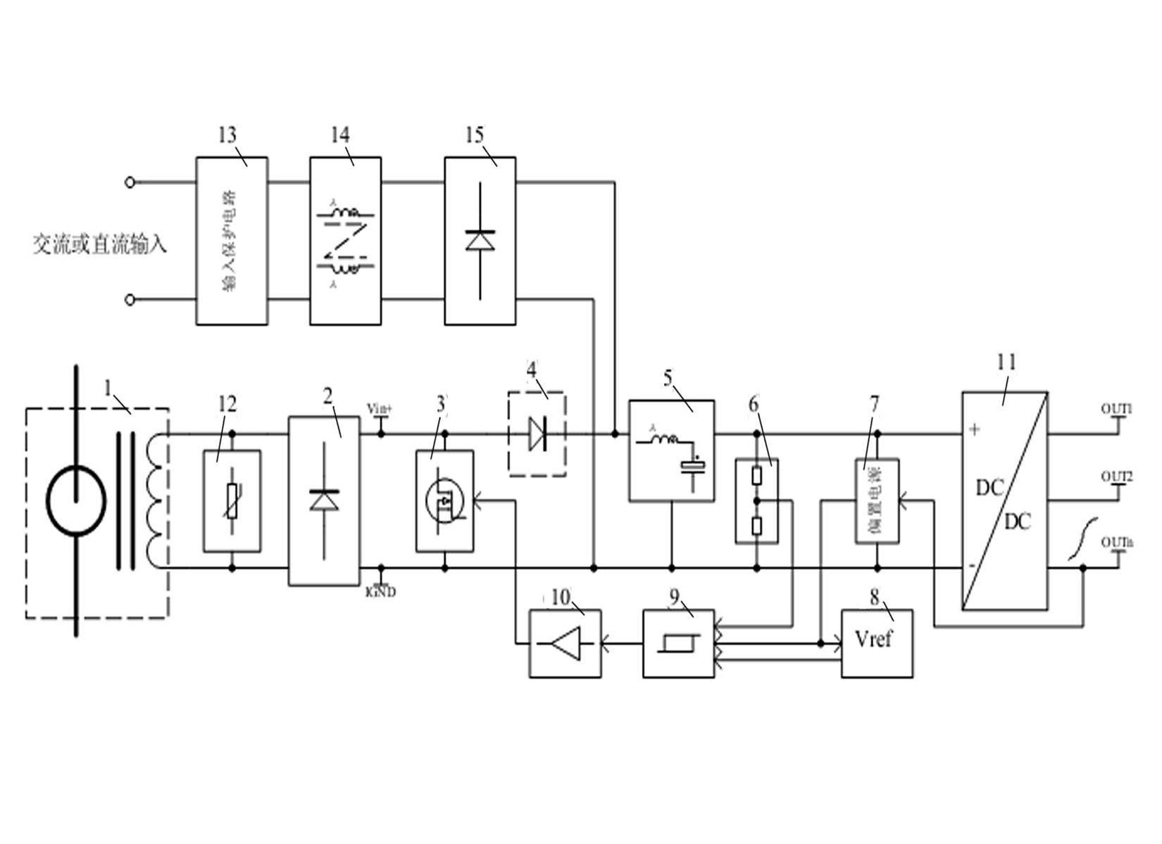
[0055] Such as figure 1 As shown, the device proposed by the present invention consists of a current transformer (CT) 1, a first bridge rectifier circuit 2, an input peak voltage suppression circuit 12, a residual current discharge switch 3, a diode 4, an LC filter circuit 5, Input voltage sampling circuit 6, bias power supply 7, reference voltage forming circuit 8, hysteresis comparison circuit 9, drive circuit 10, isolated high-frequency switch pulse width modulation DC / DC conversion multiple output regulated power supply circuit 11, AC input It is composed of a protection circuit 13, a power filter 14, and a second bridge rectifier circuit 15.

[0056]Among them, the single line of the high-voltage current loop passes through the CT. When the current Ip flows through the high-voltage loop, a current Is will be generated in the coil on the secondary side of the CT. Is≈Ip / N, N is the transformation ratio of the CT, and the current flows The circuit after the CT is converted ...


PUM


Abstract

The invention discloses a power supply device of a current transformer (CT). The power supply device comprises the CT, a first bridge type rectifier circuit, a surplus current relief switch, a diode, an LC (inductor-capacitor) filter circuit, an input voltage sampling circuit, a reference voltage forming circuit, a return difference comparing circuit, a drive circuit and an isolation high-frequency switch pulse width modulation DC/DC conversion multi-output voltage-stabilized power circuit. According to the power supply device, surplus current output by the CT is relieved by adopting an electronic switch, required energy is extracted from the CT intermittently, so that output overvoltage of the CT is limited, and the CT is prevented from saturating. Electricity taking voltage is increased by adopting a high-voltage input high-frequency switch power supply technology, thus the output current of the CT is reduced, heating of the CT and the rectifier circuit and the relief switch behind the CT is decreased, and the electricity taking efficiency is increased.

Description

technical field [0001] The invention relates to a high-frequency switching power supply technology for taking power from a current transformer (CT) and its practical application, which belongs to the application of power electronics technology in smart grid terminal equipment. Background technique [0002] In the use of smart grid terminal monitoring equipment (distribution automation system is the most typical case), how to supply power to high-voltage on-site monitoring equipment often becomes a very critical issue. For example, when monitoring high-voltage overhead lines, feeder switches, power cables, and power distribution units, there is generally no suitable low-voltage power supply nearby for monitoring equipment. Even if there is a ready-made power supply, it cannot be used. [0003] The traditional and currently most commonly used method of supplying power to these terminal monitoring equipment: use a voltage transformer (PT) to take power from a high-voltage line...

Claims


Application Information

Patent Timeline
IPC IPC(8): H02J17/00H02H9/02H02J1/10H02J5/00
Inventor 关平
Owner 深圳市深泰明科技有限公司
Why Eureka
Try Eureka