Double-shaft compensation air-cored pulse generator and pulse molding system and pulse molding method of double-shaft compensation air-cored pulse generator
A dual-axis compensation and pulse forming technology, applied in electrical components, electromechanical devices, magnetic circuit shape/style/structure, etc., to achieve miniaturization, increase energy density and power density, and resolve conflicts
- Summary
- Abstract
- Description
- Claims
- Application Information
AI Technical Summary
Problems solved by technology
Method used
Image
Examples
specific Embodiment approach 1
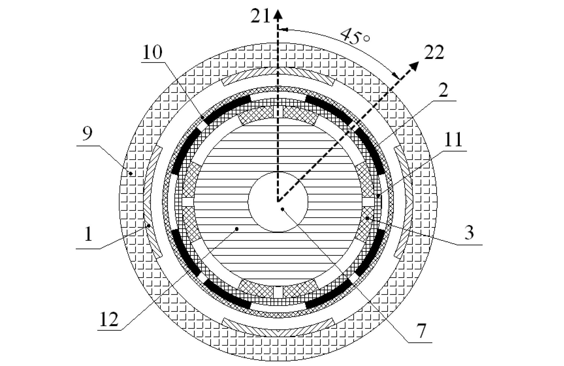
[0018] Specific implementation mode one. The following combination figure 2 Describe this embodiment, a dual-axis compensation air-core pulse generator, which includes an air-core rotor and an air-core stator, and the air-core rotor includes an excitation winding 3 and a quadrature-axis compensation winding 2, which is characterized in that: the quadrature-axis compensation winding 2 has four coils, and each coil is self-short-circuited. The axes of the two adjacent coils in the quadrature-axis compensation winding 2 and the excitation winding 3 are 45° apart in space, and the two adjacent coils The electrical angles of the two coils are arranged orthogonally by 90°.
[0019] The motor has a four-pole symmetrical structure. Under each pole, the axis 21 of the exciting winding 3 and the axis 22 of the quadrature axis compensation winding 2 have a mechanical angle difference of 45 degrees in space, and a difference of 90 degrees in electrical angle, so that the quadrature axis ...
specific Embodiment approach 2
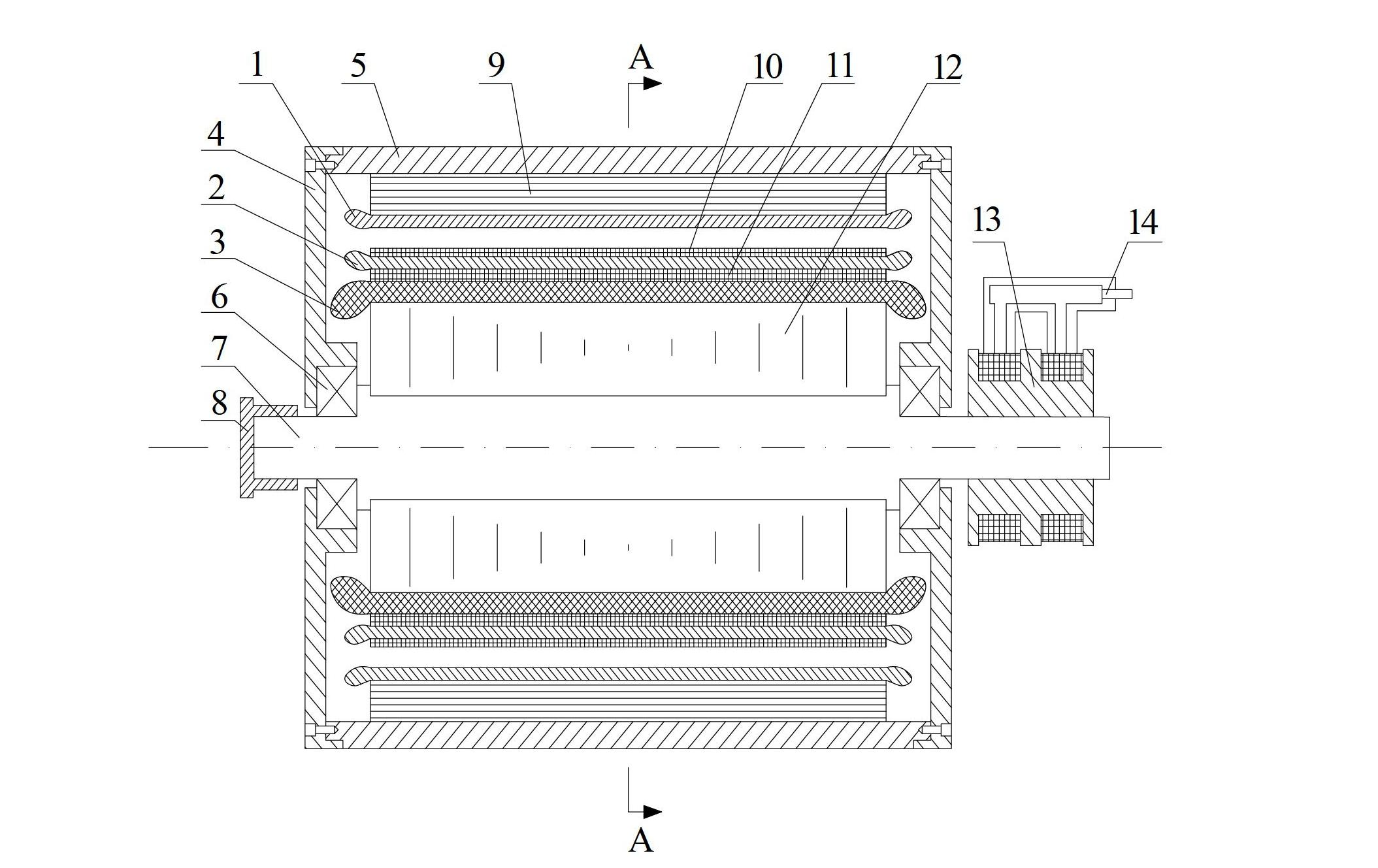
[0021] Specific implementation mode two. The following combination figure 1 and figure 2 Describe this embodiment, this embodiment is a further description of Embodiment 1, a dual-axis compensation air-core pulse generator, the motor adopts a four-pole structure, and the air-core stator is composed of an armature winding 1, an air-core The stator yoke 9 and the casing 5 are composed, and the inside of the hollow stator is a cylindrical cavity, and the hollow rotor is arranged in the cylindrical cavity;
[0022] The outer wall of the hollow stator yoke 9 is fixed on the inner wall of the casing 5; the armature winding 1 is fixed on the inner wall of the hollow stator yoke 9;
[0023] The air-core rotor includes the air-core rotor yoke 12 , the excitation winding 3 , the excitation winding bandage 11 , the quadrature axis compensation winding 2 and the compensation winding bandage 10 from the inside to the outside.
[0024] The motor described in this embodiment is a selectiv...
specific Embodiment approach 3
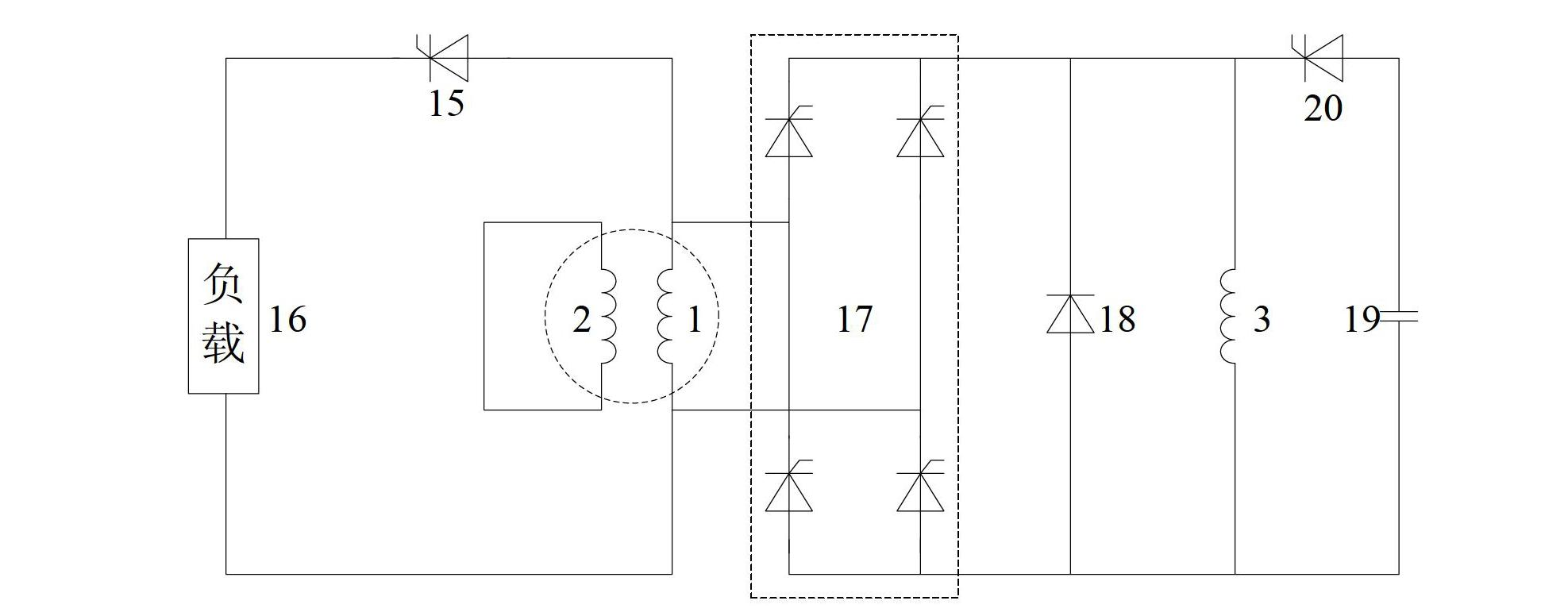
[0026] Specific implementation mode three. The following combination figure 1 and figure 2 This embodiment is described. This embodiment is a further description of the second embodiment. The armature winding 1 has four coils, and the four coils are connected in parallel.
[0027] The design speed and air gap flux density of the motor are relatively high, so the output voltage can easily meet the load demand. In order to reduce the internal inductance of the motor and output a larger current pulse, the armature winding 1 of this embodiment adopts a parallel connection method
PUM
 Abstract
Description
Claims
Application Information
 - R&D
- Intellectual Property
- Life Sciences
- Materials
- Tech Scout
- Unparalleled Data Quality
- Higher Quality Content
- 60% Fewer Hallucinations
Browse by: Latest US Patents, China's latest patents, Technical Efficacy Thesaurus, Application Domain, Technology Topic, Popular Technical Reports.
© 2025 PatSnap. All rights reserved.Legal|Privacy policy|Modern Slavery Act Transparency Statement|Sitemap|About US| Contact US: help@patsnap.com


