Device and method for steam stripping of condensate in water gas conversion process

A technology of condensate and water gas, applied in the field of coal chemical industry, can solve the problems of air pollution in the venting area, easy to corrode system pipelines, blockage and other problems, and achieve the effect of reducing corrosion, avoiding air pollution and reducing load

Active Publication Date: 2012-08-22
CHNA ENERGY INVESTMENT CORP LTD +1
View PDF3 Cites 19 Cited by
  • Summary
  • Abstract
  • Description
  • Claims
  • Application Information

AI Technical Summary

Problems solved by technology

[0009] The present invention aims to provide a condensate stripping device and method for a water-gas shift process, so as to solve the existing problems in the prior art that the shift condensate stripping sys...

Method used


Image

  • Device and method for steam stripping of condensate in water gas conversion process
  • Device and method for steam stripping of condensate in water gas conversion process
  • Device and method for steam stripping of condensate in water gas conversion process

Examples


Embodiment approach

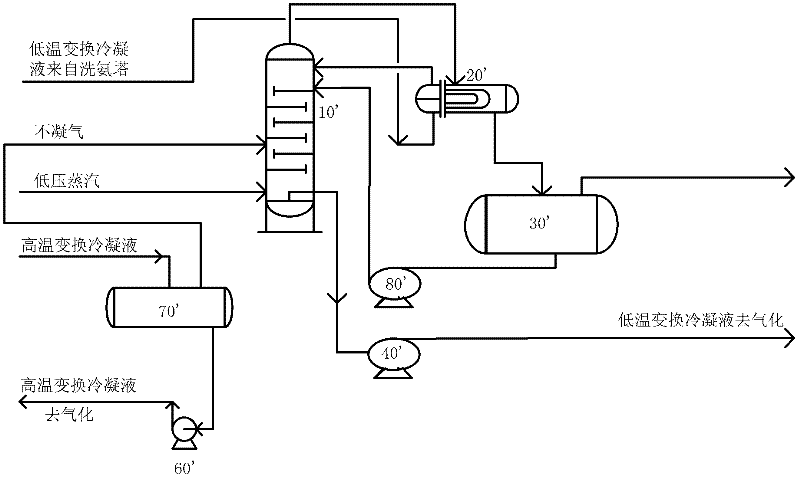
[0027] According to a typical embodiment of the present invention, a method for stripping condensate in a water-gas shift process is provided. The method comprises the following steps: sending the high-temperature condensate separated from the water-gas-water separator into a shift condensate tank for first flash evaporation; The condensed gas is sent to the flash tank together for the second flash evaporation. During the second flash evaporation, the top of the flash tank is sprayed with desalted water to wash and remove the ammonia and hydrogen sulfide in the flash steam, and then the flash steam is sent to the flash steam The treatment device performs treatment; and the condensate after being flashed by the flash tank is sent to the condensate stripping tower for stripping. The condensate flashed by the flash tank enters the condensate stripping tower for stripping after exchanging heat with the stripping gas from the condensate stripping tower through the top condenser of ...

Embodiment 1

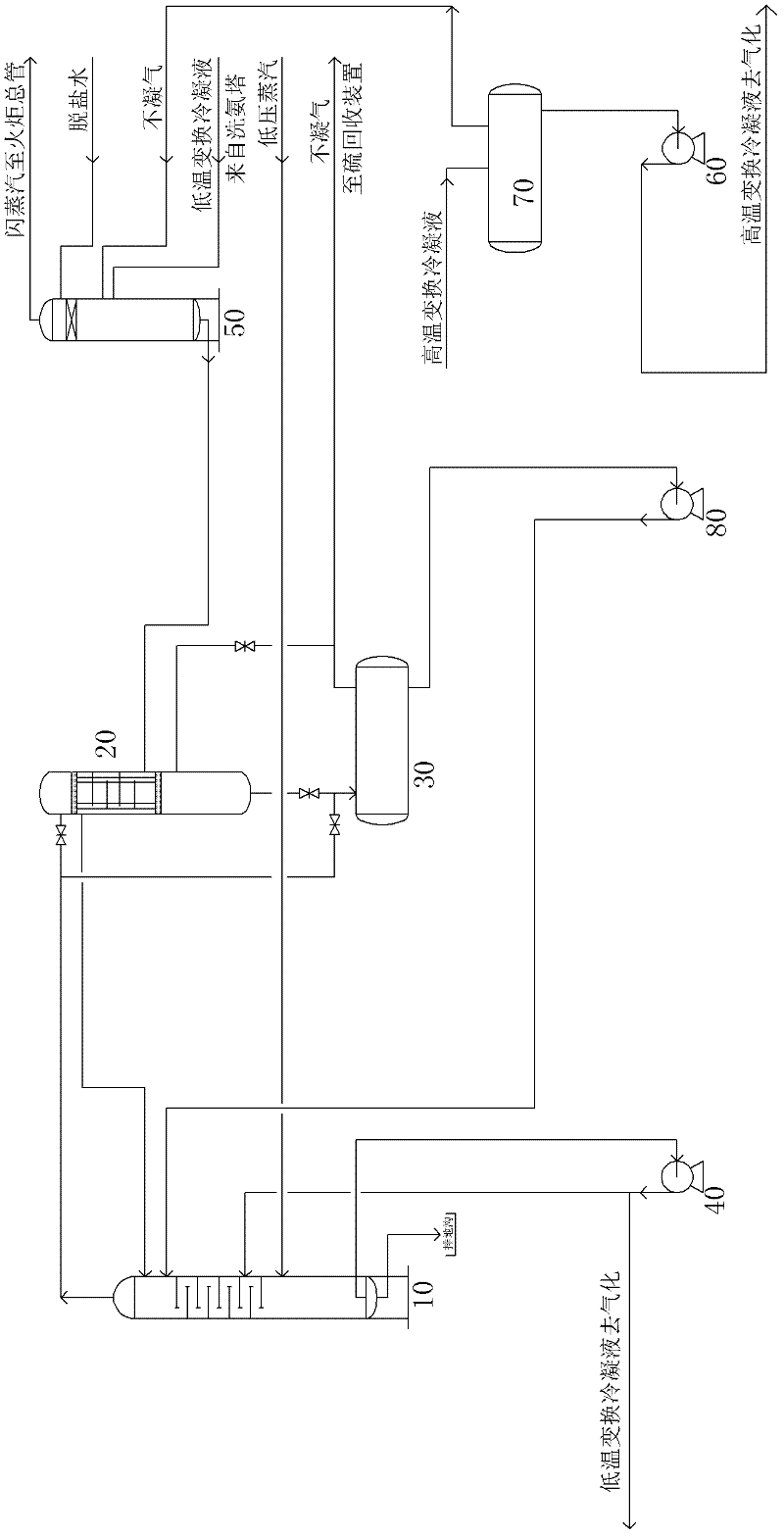
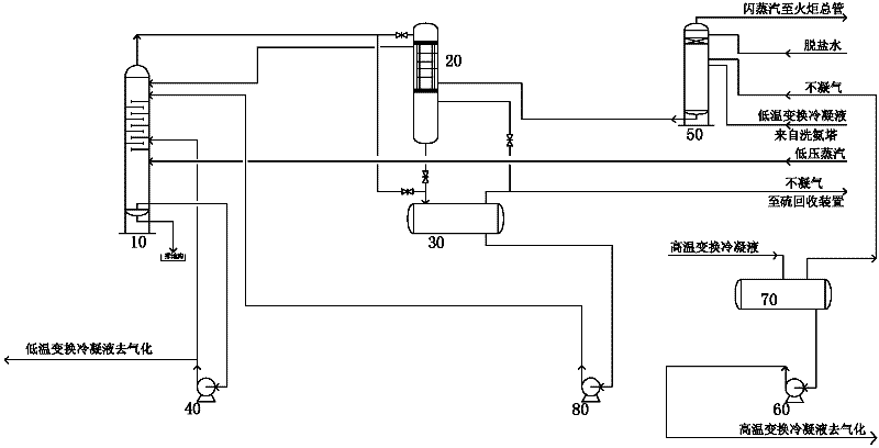
[0033] Unlike existing technologies, such as figure 2 Shown, the noncondensable gas that comes from the ammonia washing liquid at the bottom of the ammonia washing tower and the flashing of the conversion condensate tank first enters the flash tank 50, and then enters the condensate stripping tower 10 after flashing (operating condition: 0.35MPa (G ), 136 °C (overhead)) for stripping. Change the non-condensable gas (50.08kmol / hr, H 2 S content 0.137779mol%, NH 3 Content 0.109824mol%, CO 2 content 24.2mol%) and the ammonia washing liquid (8459.415kmol / hr, H 2 S content 0.0070099mol%, NH 3 Content 0.421719mol%, CO 2 content of 0.061mol%) first enters the flash tank 50 for flash evaporation, and the top of the flash tank 50 sprays desalted water to wash and remove ammonia and hydrogen sulfide in the flash steam. 3 The content is low (flash steam: 142.834kmol / hr, H 2 S content 0.2mol%, NH 3 Content 3.2mol%, CO 2 Content 7.5mol%), enter the top of condensate stripper 10 a...


PUM

PropertyMeasurementUnit
Conductivityaaaaaaaaaa

Abstract

The invention discloses a device and a method for steam stripping of condensate in a water gas conversion process. The device comprises a conversion condensate tank, a flash tank and a condensate stripping tower. The conversion condensate tank is communicated with a high-temperature condensate outlet of a water gas and water separator. The flash tank is respectively communicated with an ammonia washing liquid outlet at the bottom of an ammonia washing tower and a non-condensable gas outlet of the conversion condensate tank, a desalted water spraying device and a flash steam outlet are arranged at the top of the flash tank, and the bottom of the flash tank is provided with a condensate port. The condensate stripping tower is communicated with the condensate port of the flash tank. Using the device reduces corrosion of a top plate and a top condenser of the stripping tower, pipeline blockage and stripping tower pressure build-up, and lessens load of the stripping tower. Therefore, the device can be stably operated for a long period, maintenance frequency and cost are effectively reduced, and air pollution of an evacuation area caused by overpressure evacuation of a condensate stripping system is avoided.

Description

technical field [0001] The invention relates to the field of coal chemical industry, in particular to a water-gas shift process condensate stripping device and method. Background technique [0002] In the production of coal chemical industry, the content of carbon monoxide in the water gas produced by coal gasification is relatively high, and the ratio of carbon monoxide and hydrogen needs to be adjusted by means of conversion, so as to obtain the synthesis gas component suitable for the proportion of coal chemical production. In the shift reaction, only cheap water vapor is consumed, carbon monoxide is converted into carbon dioxide, and hydrogen is obtained in an equivalent amount. [0003] The water gas produced by coal gasification contains part of ammonia. Before further purification, the ammonia in the water gas needs to be washed with desalted water. The washed ammonia solution is sent to the condensate stripper to remove most of the dissolved ammonia, Carbon dioxide ...

Claims


Application Information

Patent Timeline
IPC IPC(8): C02F1/04C02F1/20
Inventor 余建良汤中文陈峻贤唐煜
Owner CHNA ENERGY INVESTMENT CORP LTD
Why Eureka
Try Eureka