Design method of low-phase-noise microwave wideband frequency combiner

A frequency synthesizer, low phase noise technology, applied in the field of signal interference, can solve the problems of phase noise and spurious deterioration, high output frequency, poor spurious suppression, etc., to suppress harmonic output, avoid crossover frequency, reduce small stray effect

Active Publication Date: 2012-08-29
BEIHANG UNIV
View PDF5 Cites 29 Cited by
  • Summary
  • Abstract
  • Description
  • Claims
  • Application Information

AI Technical Summary

Problems solved by technology

[0003] Frequency synthesis technology has experienced three development stages: direct analog frequency synthesis (DAFS), phase-locked frequency synthesis (PLL) and direct digital frequency synthesis (DDS). These three technologies are the technical basis of modern frequency synthesis. Each has its advantages and disadvantages, and they can complement each other very well. Therefore, the effective combination of the above three technologies constitutes a complete system of modern frequency synthesis technology, but the general DDS+PLL synthesis method also exists in various performance indicators. Contradictory
[0004] Detailed reference figure 1 As shown, the way of DDS to stimulate PLL solves the shortcomings of PLL frequency resolution (depending on DDS) and DDS output frequency is not high enough, and suppresses the out-of-band spurs. The disadvantage is that the phase noise of DDS and the spurs in the PLL The loop bandwidth has been deteriorated by 20lgN times (N is the number of frequency multi

Method used


Image

  • Design method of low-phase-noise microwave wideband frequency combiner
  • Design method of low-phase-noise microwave wideband frequency combiner
  • Design method of low-phase-noise microwave wideband frequency combiner

Examples


Embodiment Construction

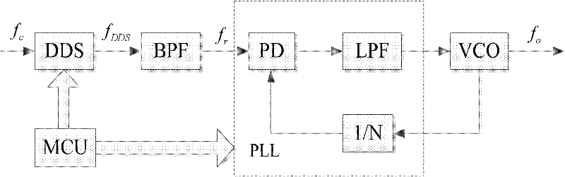
[0026] The present invention aims at inventing a frequency synthesizer, which can ensure that the phase noise, stray and harmonic output of the frequency can have a good index while having an ultra-wideband frequency output, so as to ensure the stability and purity of the output frequency . The present invention mainly carries out the implementation of scheme from the following aspects:

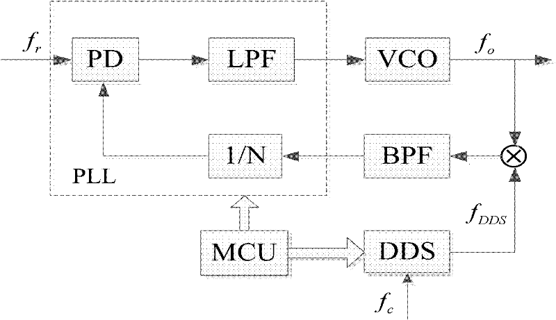
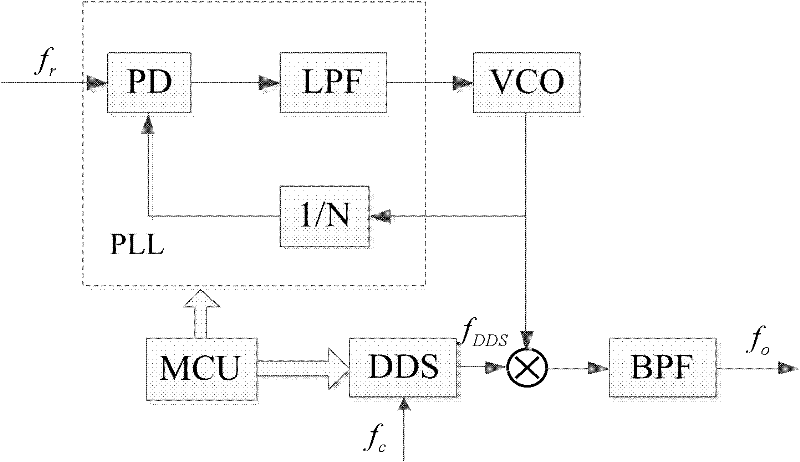
[0027] 1. Implementation of the overall plan. Through the analysis of the advantages and disadvantages of the traditional scheme, this scheme adopts the mixed frequency synthesis scheme of DDS+PLL+DAFS, which is divided into two parts for realization: the first part adopts the double phase-locked loop synthesis scheme of DDS+PLL; the second part Adopt the frequency extension scheme of DAFS.

[0028] 2. The scheme implementation of the main phase-locked loop. In order to cooperate with DAFS for frequency expansion, the main phase-locked loop selects the appropriate output frequency band for...


PUM


Abstract

The invention relates to a design method of a microwave wideband frequency combiner applied to the field of signal interference. According to the method, a DDS (Direct Digital Synthesis) + PLL (Phase Locked Loop) + DAFS (Direct Analog Frequency Synthesis) hybrid frequency synthesis mode is utilized to synthesize a 0.1-18GHz ultra wide band microwave frequency, wherein the frequency band comprises working frequencies of most of microwave signals, can meet the frequency requirement for interfering with most of the microwave signals and especially can be applied to the field of satellite interference; in a DDS+PLL link, a 4-10GHz waveband is synthesized, a double phase locked loop internal mixing synthesis mode is adopted, a secondary phase locked loop adopts a mode of stimulating PLL by DDS, and a main phase locked loop is inserted into an output frequency so as to be mixed with the output frequency; in a DAFS link, DDS+PLL output is utilized as input and expanded to a 0.1-18GHz band width by virtue of a frequency multiplication, frequency demultiplication and down frequency conversion mode so as to be output; and in the whole frequency synthesis process, through carrying out frequency control by virtue of a singlechip and an FPGA (Field Programmable Gate Array) and reasonably selecting the output frequency, frequency multiplication times and mixing frequency of each link, the final output frequency has the characteristics of low phase noise and wide band, and simultaneously the output of strays and harmonic waves can be well restrained.

Description

technical field [0001] The invention relates to a design method of a microwave frequency synthesizer in the field of signal interference, and the method is suitable for a frequency synthesizer that can output ultra-wide frequency and meet the requirements of low phase noise and the like. Background technique [0002] With the development of modern wireless communication, radar, electronic countermeasures and other fields, the system puts forward higher and higher requirements for frequency synthesizers. All countries in the world attach great importance to the development of frequency synthesizers, and frequency synthesizers with low phase noise, low spurious, high resolution, high-speed frequency conversion and ultra-wideband have become the main trend of their development. Especially in the modern military field, electronic warfare has become an important factor in determining the outcome of a war. The design and production of RF front-ends such as modern radar, communicat...

Claims


Application Information

Patent Timeline
IPC IPC(8): H03L7/18
Inventor 贾英民凌建衡
Owner BEIHANG UNIV
Why Eureka
Try Eureka