
Optical fiber amplifier with improved transient performance

A fiber amplifier and optical amplifier technology, applied in lasers, laser components, phonon exciters, etc., can solve problems such as network transient performance requirements that cannot be dynamically reconfigured, and achieve the effect of optimizing amplifier performance

Active Publication Date: 2012-09-05
XIEON NETWORKS SARL
View PDF3 Cites 0 Cited by
  • Summary
  • Abstract
  • Description
  • Claims
  • Application Information

AI Technical Summary

Problems solved by technology

However, purely feedback-based controllers cannot meet the transient performance requirements of dynamically reconfigured networks

Method used


Image

  • Optical fiber amplifier with improved transient performance
  • Optical fiber amplifier with improved transient performance
  • Optical fiber amplifier with improved transient performance

Examples


Embodiment Construction

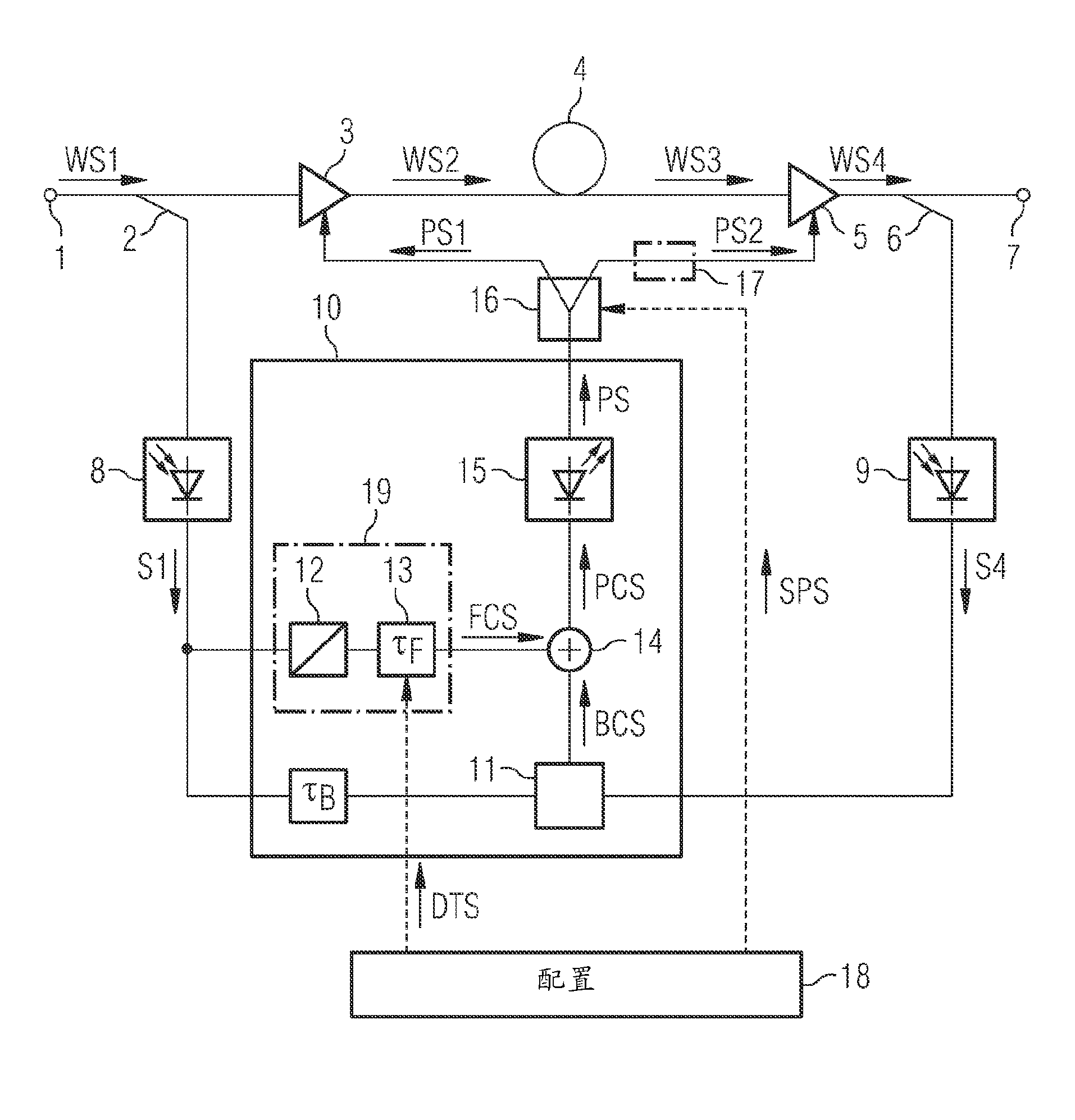
[0032] figure 1 A simplified block diagram of an optical fiber amplifier (EDFA) is illustrated. For reasons of clarity, details of fiber amplifiers (which are not part of the invention, such as couplers or isolators for inserting pump signals) are not shown.

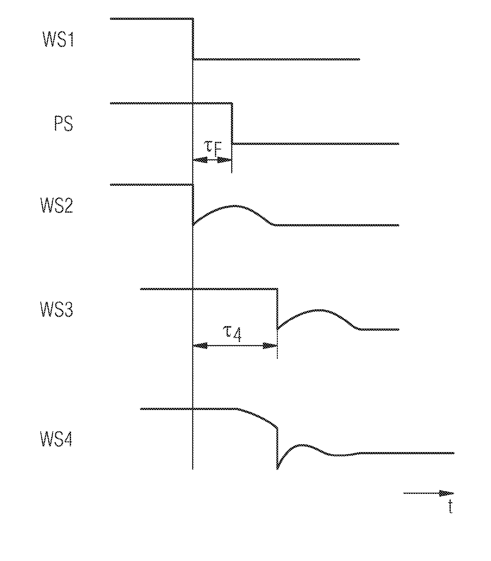
[0033] The fiber amplifier comprises two amplification stages 3 and 5 connected in series. Each stage includes doped fibers that are pumped separately. The delay element 4 (e.g., a delay of τ 4 A dispersion compensating fiber (DCF) and / or optical filter) is inserted between the amplification stages. A single pump source 15 generates a pump signal PS, and an optical power splitter 16 divides the pump signal PS into a first pump signal PS1 and a second pump signal PS2 that pump the first and second amplification stages, respectively. These stages can be forward or backward pumped. The control unit 10 controls the power of the pump signal PS generated by said single pump source 15 .

[0034] The control unit 10 utiliz...


PUM


Abstract

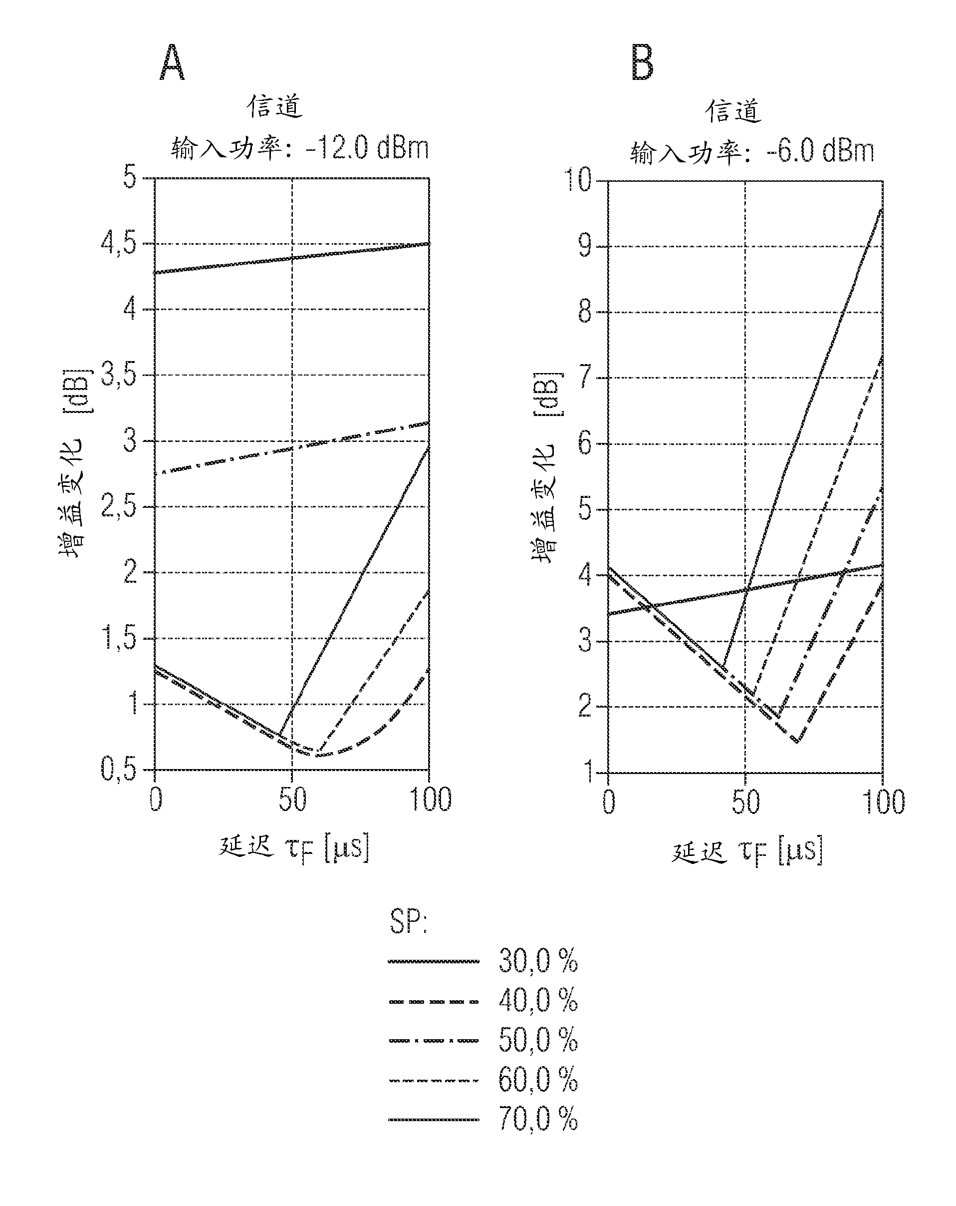
The invention describes an optical amplifier with improved transient performance comprising two amplifier stages (3, 5) and a dispersion compensating fiber (4) inserted between these stages. A control unit (10) generates a pump control signal (PCS) for a common pump source (15) pumping both amplifier stages (3, 5) via a power splitter (16). The pump control signal (PCS) has a feedforward component (FCS) with a delayed reaction. A feedforward delay time (tF) is adjusted to minimize gain variations resulting from input power drops. In a preferred embodiment, the splitting ratio of the power splitter is adjustable to achieve e.g. either optimum steady-state performance or optimum transient performance.

Description

technical field [0001] The present invention relates to a fiber amplifier with improved transient performance utilizing pump power splitting. Background technique [0002] Optical fiber amplifiers are widely used for signal amplification in optical data transmission networks based on wavelength division multiplexing (WDM). Changes in network configuration, component failures, fiber breaks, or protection switching can cause sudden changes in optical input power. These changes result in rapid changes in the output power of the amplifier, which can be transferred to other wavelengths due to the nonlinear fiber effects and non-ideal dynamic properties of erbium-doped fiber amplifiers (EDFAs). These changes can propagate to other locations, causing fluctuations in optical power across the network and possibly oscillations. Thus, even channels not directly affected by handover operations or failures may experience some performance degradation at the receiver. [0003] In additi...

Claims


Application Information

Patent Timeline
Patent Type & Authority Applications(China)
IPC IPC(8): H04B10/17H01S3/067H04B10/294
CPCH01S3/06725H01S3/06758H01S3/094061H04B10/2942H01S3/10015H01S3/13013H01S3/10069
Inventor L.拉普
Owner XIEON NETWORKS SARL
Learn More