Ring-shaped fluidized bed reactor

A bed reactor and annular flow technology, applied in the field of annular fluidized bed reactors, can solve the problems of complex fluid mechanics, transfer phenomena, reducing the chance of gas-solid phase contact, cumbersome overall structure of the reactor, etc., and achieve effective use of heat sources. , The working state can be adjusted, and the effect of improving the reaction conversion rate

Inactive Publication Date: 2012-09-12
BEIJING FORESTRY UNIVERSITY
View PDF4 Cites 7 Cited by
  • Summary
  • Abstract
  • Description
  • Claims
  • Application Information

AI Technical Summary

Problems solved by technology

[0004] Due to the inherent characteristics of fluidization technology and the diversity of factors affecting the fluidization process, the fluidized bed has many disadvantages for the reactor: 1) Due to the violent circulation and agitation of solid particles and air bubbles in the continuous flow process, There is a wide residence time distribution in both the gas phase and the solid phase, resulting in inappropriate product distribution, which reduces the conversion rate of the target product; 2) The reactant passes through the bed in the form of bubbles, reducing the gas-solid phase. 3) When a solid catalyst is used, the violent impact and friction of the bed material particles during the flow process accelerates the pulverization of the catalyst, c...

Method used


Image

  • Ring-shaped fluidized bed reactor
  • Ring-shaped fluidized bed reactor
  • Ring-shaped fluidized bed reactor

Examples


Embodiment Construction

[0020] The present invention will be described in detail below with reference to the accompanying drawings and examples.

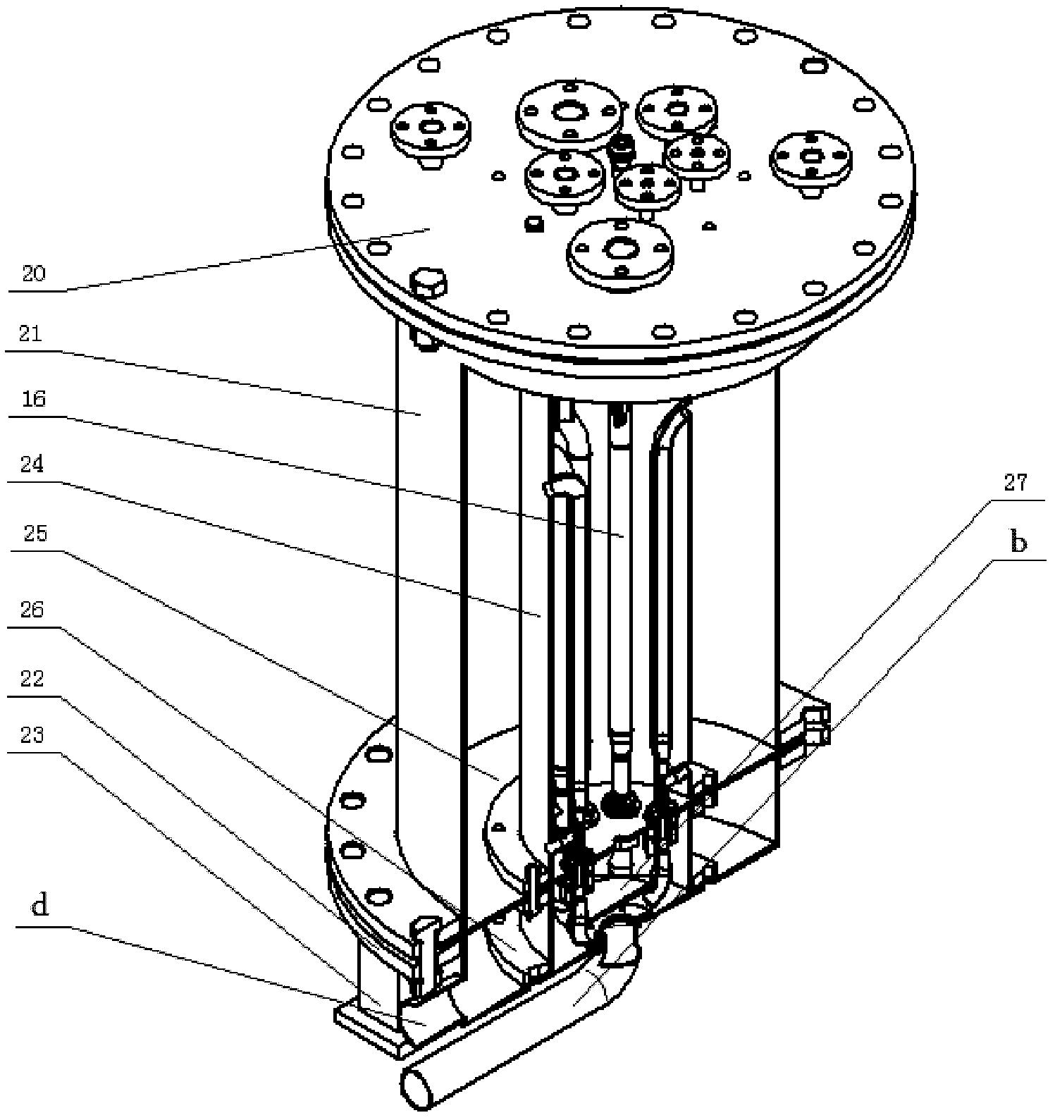
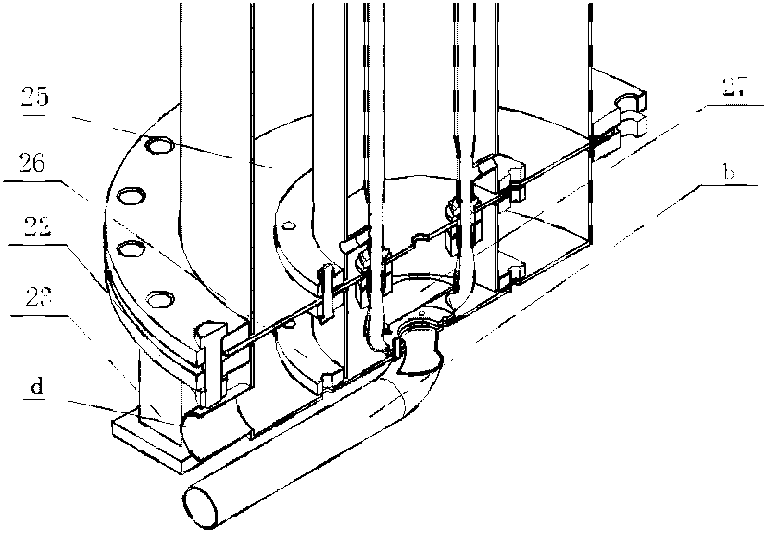
[0021] as attached figure 1 and attached figure 2 As shown, the present invention provides a kind of annular fluidized bed reactor, and this reactor comprises top cover 20, reactor shell 21, bottom shell 22, support 23, combustion chamber 24, air distribution plate 25, air distribution cabin Plate 26, gas distribution chamber 27 and circulation speed-increasing pipe 16, peripheral equipment includes cyclone separator (playing the role of gas-solid separation) and fan;

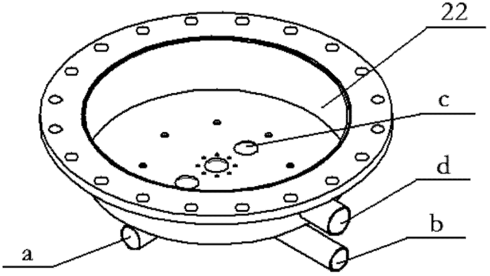
[0022] Wherein the reactor shell 21 is a cylindrical body with flanges welded at the upper and lower ends of the peripheral surface; the combustion chamber 24 is also a cylindrical body with flanges welded at the upper and lower ends of the peripheral surface, and eight Mounting holes; if attached image 3 As shown, the bottom shell 22 is a cylinder with a flange welded on the upper end...


PUM


Abstract

The invention provides a ring-shaped fluidized bed reactor, belonging to the technical field of fluidized bed reactors. The ring-shaped fluidized bed reactor comprises a top cover, a reactor outer shell, a bottom shell, a support, a combustion chamber, an air distributing plate and an air distributing cabin partition and also comprises circulatory speed increasing pipes and an air distributing cabin, wherein peripheral equipment comprises a cyclone separator and a fan; the lower end of the reactor outer shell is provided with the air distributing plate and then is fixedly connected with the bottom shell; the combustion chamber is sheathed in the reactor outer shell; the axis of the reactor outer shell and the axis of the combustion chamber are consistent, and a ring-shaped reaction area is formed between the reactor outer shell and the combustion chamber; the circulatory speed increasing pipes are uniformly distributed in the combustion chamber, the upper ends of the circulatory speed increasing pipes are communicated with the ring-shaped reaction area, and the lower ends of the circulatory speed increasing pipes penetrate through the air distributing plate; the bottom shell is internally provided with the air distributing cabin partition which is internally provided with the air distributing cabin; and bending pipes on the circumferential surface of the air distributing cabin are communicated with the lower ends of the circulatory speed increasing pipes. The ring-shaped fluidized bed reactor provided by the invention has the advantages that the combustion chamber is arranged in the reactor outer shell and is internally provided with the circulatory speed increasing pipes, so that the space can be saved, the heat loss can be reduced, meanwhile the internal circulation of fluid is enhanced, and the heat transferring efficiency and the reaction conversion rate of the reactor are increased.

Description

technical field [0001] The invention relates to a reactor, in particular to an annular fluidized bed reactor, and belongs to the technical field of fluidized bed reactors. Background technique [0002] The fluidized bed reactor is a reactor that uses gas or liquid to pass through the granular solid layer to keep the solid particles in a suspended state and perform a gas-solid phase reaction process or a liquid-solid phase reaction process. When used in a gas-solid system , also known as ebullated bed reactor. [0003] Gas-solid fluidization technology is an important branch of chemical engineering. Since the 1920s, fluidized bed technology has been used in many industrial fields due to its unique advantages, such as efficient heat and mass transfer, uniform temperature field, large particle processing capacity, and wide operating range. have been widely used, and still have very good industrial prospects. So far, many researchers have established cold state and hot state ...

Claims


Application Information

Patent Timeline
IPC IPC(8): B01J8/24
Inventor 王霄司慧任学勇常建民
Owner BEIJING FORESTRY UNIVERSITY
Why Eureka
Try Eureka