Overrunning clutch for confluence mechanism of double-turbine hydraulic torque converter

A hydraulic torque converter and overrunning clutch technology, applied in clutches, one-way clutches, mechanical equipment, etc., can solve the problems of high manufacturing precision, wear failure, unreasonable, etc., to eliminate the influence of machining accuracy and reduce diameter. Centrifugal force, compact structure

Inactive Publication Date: 2012-09-12
JILIN UNIV
View PDF7 Cites 6 Cited by
  • Summary
  • Abstract
  • Description
  • Claims
  • Application Information

AI Technical Summary

Problems solved by technology

The outer ring gear 15 and the intermediate shaft gear 17 are positioned through two deep groove ball bearings. At the same time, under low speed and heavy load conditions, the outer ring gear 15 and the intermediate shaft gear 17 are rigidly locked by the roller 19, which causes the outer ring There are three positioning points between the gear 15 and the intermediate shaft gear 17. This over-positioning method puts forward very strict requirements on manufacturing accuracy, which is also unreasonable.
[0008] Third, high manufacturing precision is required
The different rollers 19 are separated by the spacer ring 18 with indexing grooves and positioned on the cam surface of the inner star wheel 16. If the indexing grooves of the spacer ring 18 and the indexing accuracy of the cam surface of the inner star wheel 16 cannot meet the requirements, It will cause only part of the rollers 19 to participate in the load, which will easily cause wear and tear failure

Method used


Image

  • Overrunning clutch for confluence mechanism of double-turbine hydraulic torque converter
  • Overrunning clutch for confluence mechanism of double-turbine hydraulic torque converter
  • Overrunning clutch for confluence mechanism of double-turbine hydraulic torque converter

Examples


Embodiment 1

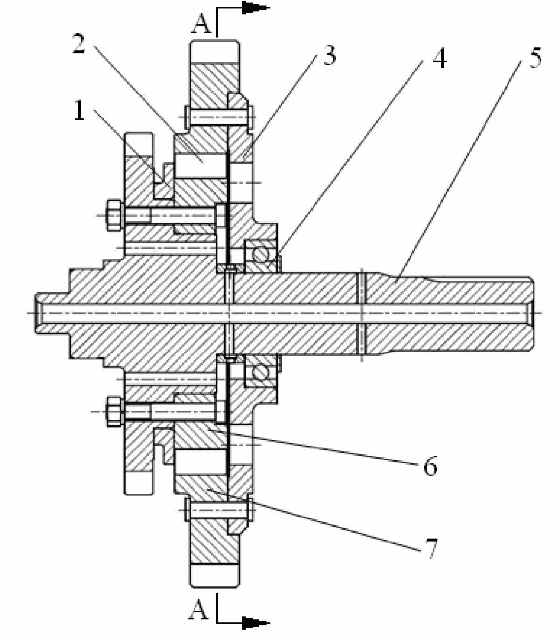
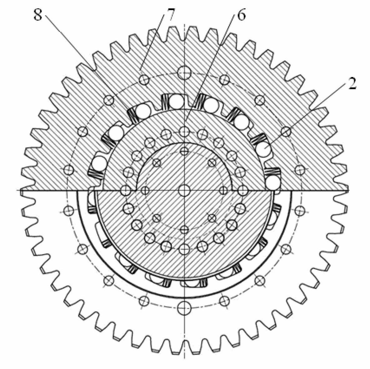
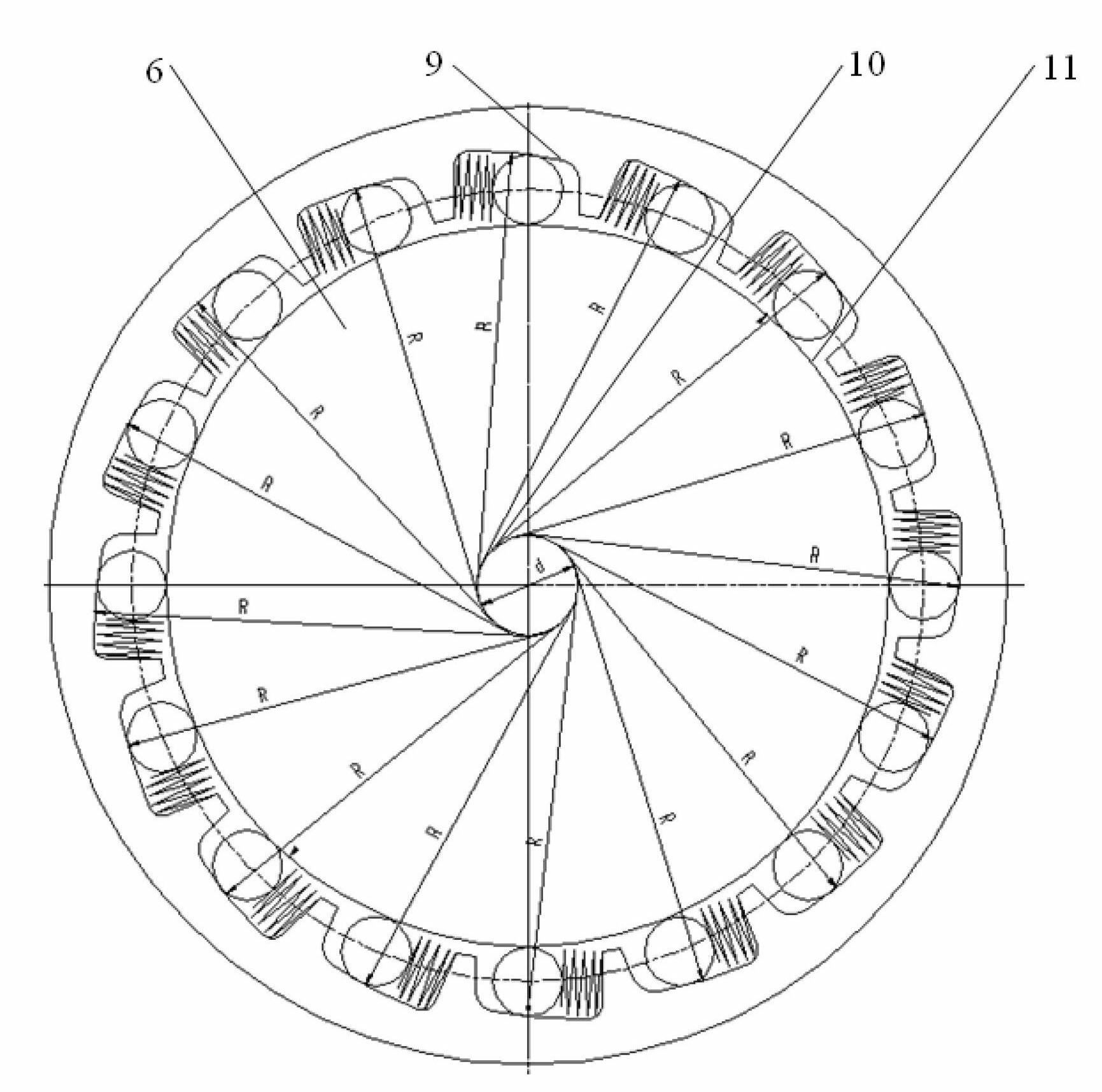
[0040] In the overrunning clutch of the converging mechanism of the twin-turbo torque converter, the cam surface 9 is set in the inner hole of the outer ring gear 7, the outer surface of the inner star wheel 6 is a cylindrical surface 11, and the roller 2 is installed on the cam surface 9 of the outer ring gear 7 In the cavity formed by the outer cylindrical surface 11 of the inner star wheel 6, a spring 8 is installed at one end of the roller 2 to push the roller 2 to remain on the wedging side of the cavity, and the outer ring gear 7, the inner star wheel 6 and the roller 2 form a self-locking mechanism, the inner star wheel 6 can only rotate in one direction relative to the outer ring gear 7, and lock in the opposite direction.

[0041] The diameter of the outer cylindrical surface 11 of the inner star wheel 6 is 165 mm, the diameter of the roller 2 is φ = 15 mm, the radius R of the cam surface 9 of the outer ring gear 7 is an arc surface of R = 97 mm, and the center of the ...

Embodiment

[0046] In the overrunning clutch of the converging mechanism of the twin-turbo torque converter, the cam surface 9 is set in the inner hole of the outer ring gear 7, the outer surface of the inner star wheel 6 is a cylindrical surface 11, and the roller 2 is installed on the cam surface 9 of the outer ring gear 7 In the cavity formed by the outer cylindrical surface 11 of the inner star wheel 6, a spring 8 is installed at one end of the roller 2 to push the roller 2 to remain on the wedging side of the cavity, and the outer ring gear 7, the inner star wheel 6 and the roller 2 form a self-locking mechanism, the inner star wheel 6 can only rotate in one direction relative to the outer ring gear 7, and lock in the opposite direction.

[0047] The diameter of the outer cylindrical surface 11 of the inner star wheel 6 is 168mm, the diameter of the roller 2 is φ=18mm, the radius R of the cam surface 9 of the outer ring gear 7 is an arc surface of R=102mm, and the center of the arc is...


PUM


Abstract

The invention relates to an overrunning clutch for a confluence mechanism of a double-turbine hydraulic torque converter. A cam surface of a self-locking mechanism is arranged in an inner bore of an outer ring gear, and an inner planetary gear is of a cylindrical surface. The outer ring gear is positioned on a middle shaft gear and positioned by utilizing self locking of a deep groove ball journal and a pin roller, thus changing the existing three-point over-positioning structure. The outer ring gear of the overrunning clutch has low rotation speed, and the pin roller is arranged on the cam surface of the outer ring gear, thus greatly reducing the self radial centrifugal force; and furthermore, no normal action force exists in the contact process of the pin roller and the inner planetary gear, thus avoiding frictional wear and prolonging the service life. The inner planetary gear and the middle shaft gear adopt an equal length locating surface structure, and the stress surface can not generate plastic deformation due to increasing of a load, thus improving the bearing capacity of parts. The left side of the pin roller is limited by a baffle plate and the right side of the pin roller is limited by a supporting disc in the axial direction. The structure form that the cam surface of the existing overrunning clutch is arranged on the inner planetary gear is changed, the machining is simple and convenient and the manufacturing cost is low.

Description

Technical field: [0001] The invention relates to an overrunning clutch of a twin-turbine hydraulic torque converter of a loader in engineering machinery, in particular to an overrunning clutch of a confluence mechanism of a hydraulic torque converter. Background technique [0002] More than 80% of the existing wheel loaders use twin-turbine hydraulic torque converters (as attached image 3 ) to achieve stepless speed change and improve work productivity. The power of this twin-turbine hydraulic torque converter is input by the pump wheel 12, and is output to the gearbox from the intermediate shaft gear (17). There are two turbines in the middle to output power, wherein the stage I turbine 14 outputs power to the outer ring gear 15 through a pair of gear pairs, and the stage II turbine 13 outputs power to the countershaft gear 17 through another pair of gear pairs. There is a one-way inner star wheel 16 self-locking mechanism between the outer ring gear 15 and the intermedia...

Claims


Application Information

Patent Timeline
Patent Type & Authority Applications(China)
IPC IPC(8): F16D41/066
Inventor 王松林马文星刘春宝宋建军才委
Owner JILIN UNIV
Why Eureka
Try Eureka