
Heat flow simulation test device of crystallizer meniscus horizontal heat transfer

A heat transfer heat flow and simulation test technology is applied in the field of a mold meniscus horizontal heat transfer heat flow simulation test device to achieve the effects of accurate and controllable shell temperature, low manufacturing cost, and convenient equipment use.

Inactive Publication Date: 2012-09-12
CENT SOUTH UNIV
View PDF2 Cites 13 Cited by
  • Summary
  • Abstract
  • Description
  • Claims
  • Application Information

AI Technical Summary

Problems solved by technology

[0006] The technical problem to be solved by the present invention is to provide a mold meniscus horizontal heat transfer and heat flow simulation test device to solve the problems of molten steel, mold slag and crystallizer in the existing iron and steel metallurgical continuous casting process. The inter-heat flow cannot be monitored, and the thermodynamic changes of the mold slag during the heat transfer process cannot be observed in situ, and the actual working conditions in the continuous casting process can be reproduced to provide a basis for research, testing and evaluation of the heat transfer and heat conduction of the mold slag melt material performance, as well as research on the influence of parameters such as crystallizer coating material and thickness on heat transfer, and create conditions for a reasonable evaluation of the heat energy utilization efficiency of the metallurgical process

Method used


Image

  • Heat flow simulation test device of crystallizer meniscus horizontal heat transfer
  • Heat flow simulation test device of crystallizer meniscus horizontal heat transfer
  • Heat flow simulation test device of crystallizer meniscus horizontal heat transfer

Examples


Embodiment Construction

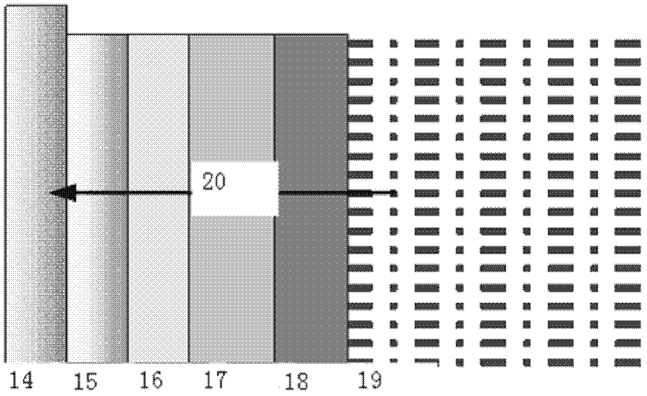
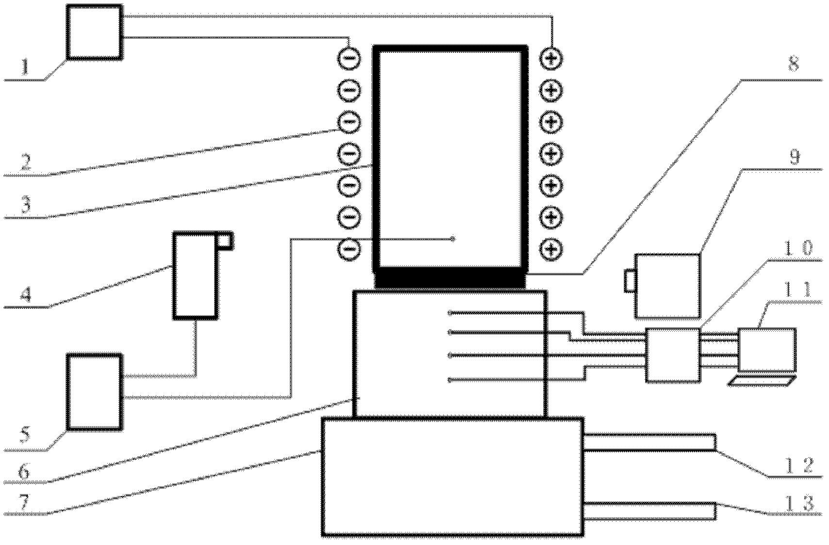
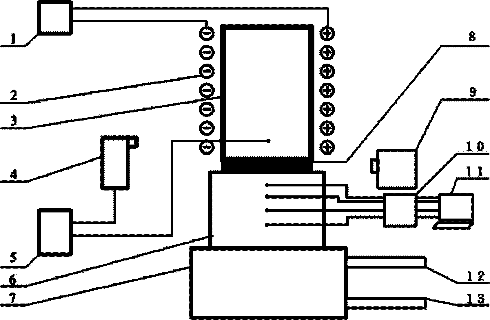
[0013] Such as figure 2 As shown, an embodiment of the present invention includes a blank shell 3, a crystallizer 6, a computer 11, a base 7, two temperature collectors 4 and 10, two temperature control modules 1 and 5, and the crystallizer 6 is fixed on the base 7, The mold shell 3 is fixed above the mold 6, and a mold slag sample 8 is fixed between the mold 6 and the mold shell 3. A camera 9 is installed on one side of the mold slag sample 8, and an induction heating coil 2 is installed on both sides of the mold shell 3. The heating coil 2 is connected to the first temperature control module 1, the thermocouple is inserted in the blank shell 3 and the crystallizer 6, and the second temperature control module 5 is respectively connected to the thermocouple in the blank shell 3 and the first temperature collector 4 Connection, the thermocouple in the crystallizer 6 is connected with the computer 11 through the second temperature collector 10, and the base 7 is provided with a...


PUM

PropertyMeasurementUnit
diameteraaaaaaaaaa

Abstract

The invention discloses a heat flow simulation test device of crystallizer meniscus horizontal heat transfer, which comprises a billet casing, a crystallizer, a computer, a base, two temperature collectors and two temperature control modules, wherein the crystallizer is fixed on the base, the billet casing is fixed above the crystallizer, a casting powder sample is fixed between the crystallizer and the billet casing, and a camera is arranged on one side of the casting powder sample. Induction heating devices are arranged on two sides of the billet casing and connected with the first temperature control module. A thermocouple is respectively inserted into the billet casing and the crystallizer, the second temperature control module is respectively connected with the thermocouple in the billet casing and the first temperature collector, and the thermocouple in the crystallizer is connected with the computer through the second temperature collector. A water inlet pipe and a water outlet pipe are arranged on the base. The heat flow simulation test device solves problems that heat flow among liquid steel, casting powder and the crystallizer in the existing steel metallurgy continuous casting process cannot be monitored and thermodynamic change of casting powder in the heat transfer process cannot be observed in situ.

Description

technical field [0001] The invention relates to the field of testing the heat transfer performance of silicate materials, in particular to a simulation test device for horizontal heat transfer and heat flow on the meniscus of a crystallizer. Background technique [0002] In the continuous casting process, the meniscus of the initial solidification point of the slab is a crucial place, because it is not only the growth point of the initial solidification shell, but also the breeding ground for various surface defects. In order to improve the surface quality of the slab, since the birth of continuous casting technology, the heat transfer and solidification behavior in this area has been paid attention to, and two researches have been carried out. and the temperature field of the slab; on the other hand, the temperature of the mold is measured through laboratory or industrial scale experiments. [0003] However, since this area is a multi-component (steel, mold slag, mold), mu...

Claims


Application Information

Patent Timeline
Patent Type & Authority Applications(China)
IPC IPC(8): G01N25/20
Inventor 王万林马范军黄道远
Owner CENT SOUTH UNIV
Learn More