
Self-adaptive composite mechanism tunneling field effect transistor (TFET) and preparation method thereof

A tunneling field effect and transistor technology, which is applied in semiconductor devices, semiconductor/solid-state device manufacturing, electrical components, etc., can solve the problems of small on-state current and limit the application of TFET devices, achieve high on-state current, and suppress bipolar effect, the effect of steep subthreshold characteristics

Active Publication Date: 2015-03-11
PEKING UNIV
View PDF3 Cites 0 Cited by
  • Summary
  • Abstract
  • Description
  • Claims
  • Application Information

AI Technical Summary

Problems solved by technology

However, due to the limitation of source junction tunneling probability and tunneling area, TFET faces the problem of small on-state current, which is far inferior to traditional MOSFET devices, and TFET has bipolar conduction effect, which greatly limits the performance of TFET devices. application

Method used


Image

  • Self-adaptive composite mechanism tunneling field effect transistor (TFET) and preparation method thereof
  • Self-adaptive composite mechanism tunneling field effect transistor (TFET) and preparation method thereof
  • Self-adaptive composite mechanism tunneling field effect transistor (TFET) and preparation method thereof

Examples


Embodiment Construction

[0036] The present invention will be further described below by example. It should be noted that the purpose of the disclosed embodiments is to help further understand the present invention, but those skilled in the art can understand that various replacements and modifications are possible without departing from the spirit and scope of the present invention and the appended claims of. Therefore, the present invention should not be limited to the content disclosed in the embodiments, and the protection scope of the present invention is subject to the scope defined in the claims.

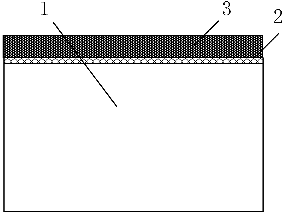
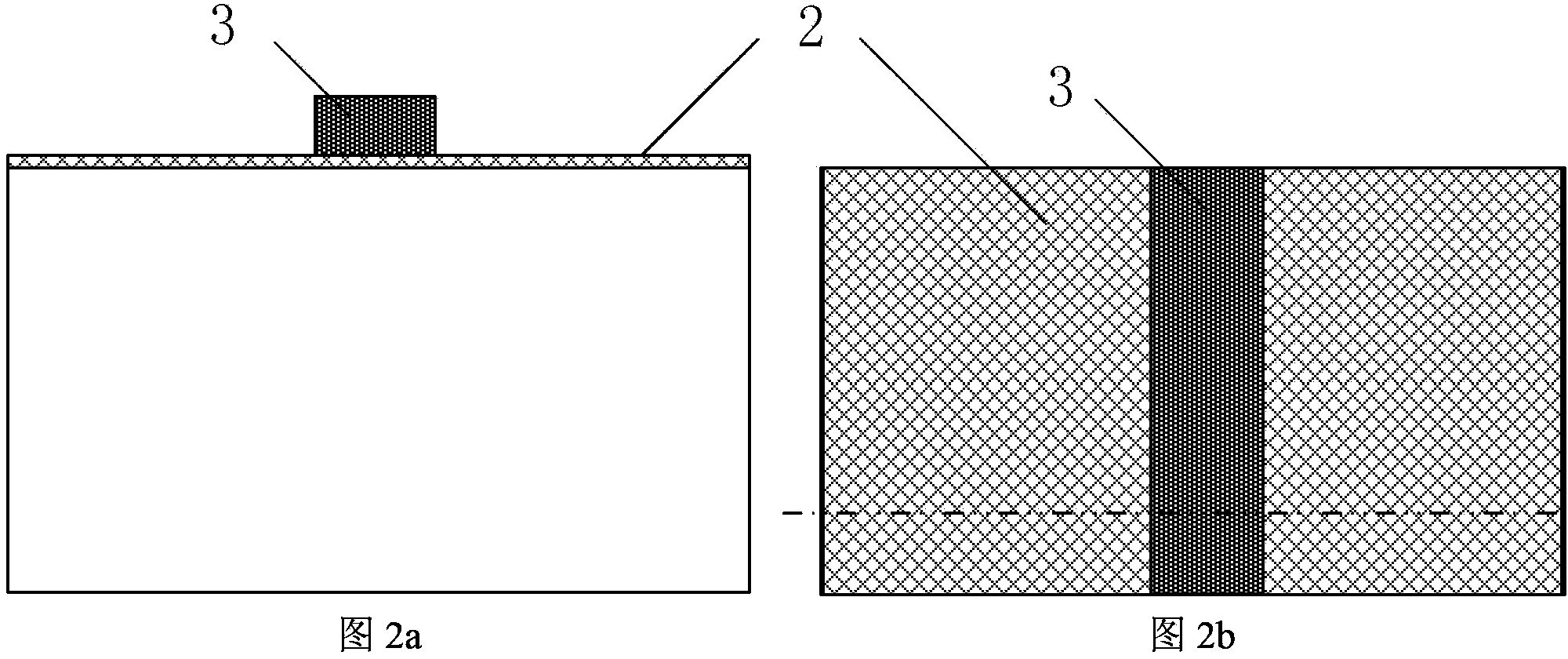
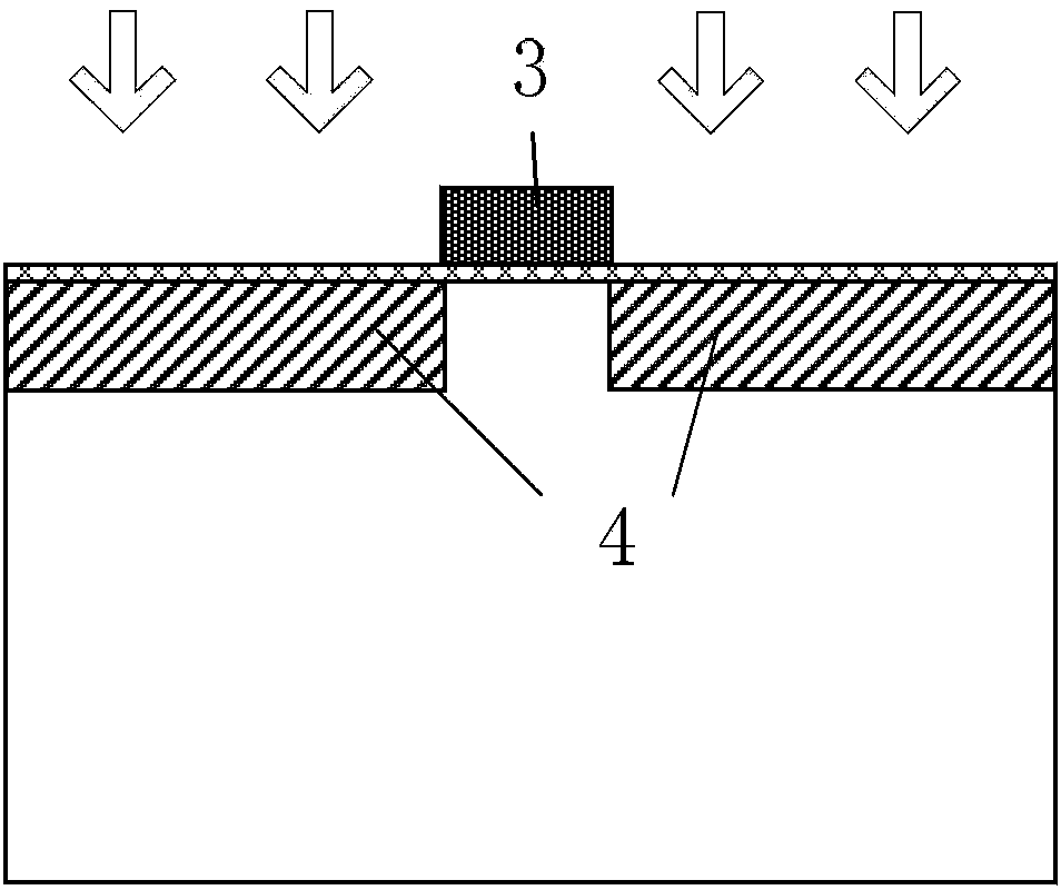
[0037] A specific example of the preparation method of the present invention includes Figure 1 to Figure 4b Process steps shown:

[0038] 1. On the bulk silicon wafer silicon substrate 1 with the crystal orientation of (100), the active region isolation layer is fabricated using shallow trench isolation technology, and the doping concentration of the substrate is lightly doped; then a layer of gat...


PUM


Abstract

The present invention relates to the field of tunneling field effect transistor logic devices and circuits in a CMOS ultra large scale integrated (ULSI) circuit. Disclosed are a tunneling field effect transistor and manufacturing method thereof. The tunneling field effect transistor is: for an N type transistor, P+ is injected, on the basis of doping N-, into one side of a doped source area close to the edge of a control gate (3), so that the original doped N- of the injected part is completely compensated as P+; and for a P type transistor, N+ is injected, on the basis of doping P-, into one side of the doped source area close to the edge of the control gate (3), so that the original doped P- of the injected part is completely compensated as N+. Through the doped injection twice of different concentrations into the source area, the device structure of the tunneling field effect transistor effectively combines the characteristics of large conducting current of an MOSFET, thus improving the on-state current of the device, and self-adaptively achieving threshold adjustment of the MOSFET and TFET parts of the device.

Description

technical field [0001] The invention belongs to the field of field-effect transistor logic devices and circuits in CMOS ultra-large integrated circuits (ULSI), and in particular relates to a tunneling field-effect transistor that uses an adaptive method to effectively combine metal-oxide layer-silicon field-effect transistor (MOSFET) currents (TFET) and its preparation method. Background technique [0002] As the size of MOSFET continues to shrink, when it enters the nanometer scale, the negative effects such as the short channel effect of the device become more and more serious, which makes the off-state leakage current of the device continue to increase. At the same time, because the sub-threshold slope of the traditional MOSFET is limited by the thermoelectric potential and cannot be reduced synchronously with the reduction of the device size, there is a theoretical limit of 60mV / dec, which makes the leakage current further increase with the reduction of the power supply ...

Claims


Application Information

Patent Timeline
Patent Type & Authority Patents(China)
IPC IPC(8): H01L29/78H01L29/08H01L21/336
CPCH01L29/7391H01L21/823814H01L21/823807H01L21/26513H01L21/266H01L21/28194H01L21/28202H01L21/28211H01L21/324H01L29/0649H01L29/0847H01L29/66325H01L29/66977
Inventor 黄如黄芊芊詹瞻邱颖鑫王阳元
Owner PEKING UNIV
Learn More