

Iron ore sinter mixture distribution method
A technology for sintering mixtures and iron ore, which is applied in furnaces, lighting and heating equipment, furnace types, etc., can solve problems such as the inability to effectively realize fuel segregation and difficult control of magnetic field strength, and achieve improved stress conditions and moving rails, Effect of Improving Magnetic Susceptibility
- Summary
- Abstract
- Description
- Claims
- Application Information
AI Technical Summary
Problems solved by technology
Method used
Image

Examples
Embodiment 1
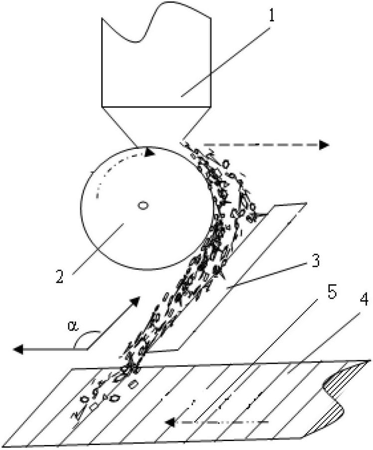
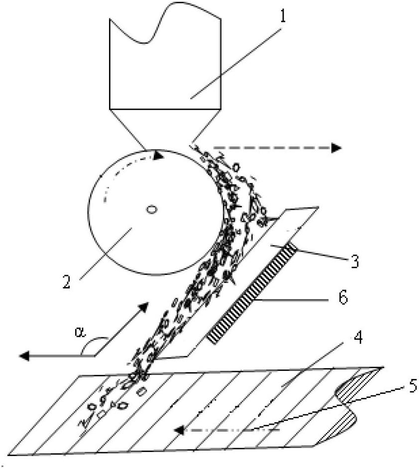
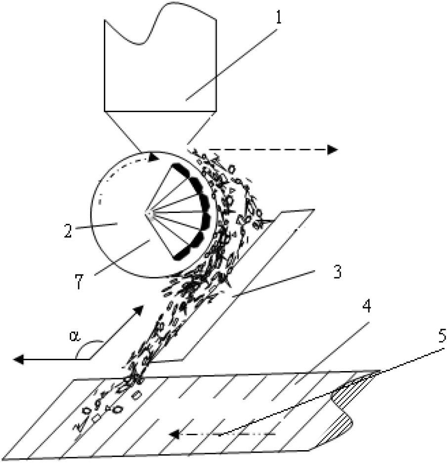
[0038] See attached Figure 4 , a distributing device for iron ore sintering mixture in the present invention, comprising a round roller feeder-reflecting plate distributor, the distributing roller in the round roller feeder is provided with a permanent magnet composed of alternating polarities Magnetic system, the reflective plate in the reflective plate distributor is below the horizontal axis of the distribution roller and parallel to the tangent line passing the circumference below the horizontal axis of the distribution roller, and the axis of the reflective plate is in line with the moving direction of the sintering machine trolley The included angle α is 45°; the magnetic system is composed of 6 NdFeB permanent magnets with alternating polarities, and the magnetic field strength formed on the circumferential surface of the distribution roller is 300Gs~2000Gs, and the distribution range on the circumferential surface of the distribution roller is The contact point betwee...
Embodiment 2
[0040] See attached Figure 4 , a distributing device for iron ore sintering mixture in the present invention, comprising a round roller feeder-reflecting plate distributor, the distributing roller in the round roller feeder is provided with a permanent magnet composed of alternating polarities Magnetic system, the reflective plate in the reflective plate distributor is below the horizontal axis of the distribution roller and parallel to the tangent line passing the circumference below the horizontal axis of the distribution roller, and the axis of the reflective plate is in line with the moving direction of the sintering machine trolley The included angle α is 45°; the magnetic system is composed of 6 NdFeB permanent magnets with alternating polarities, and the magnetic field strength formed on the circumferential surface of the distribution roller is 300Gs~2000Gs, and the distribution range on the circumferential surface of the distribution roller is The contact point betwee...
Embodiment 3
[0042] See attached Figure 4 , a distributing device for iron ore sintering mixture in the present invention, comprising a round roller feeder-reflecting plate distributor, the distributing roller in the round roller feeder is provided with a permanent magnet composed of alternating polarities Magnetic system, the reflective plate in the reflective plate distributor is below the horizontal axis of the distribution roller and parallel to the tangent line passing the circumference below the horizontal axis of the distribution roller, and the axis of the reflective plate is in line with the moving direction of the sintering machine trolley The included angle α is 45°; the magnetic system is composed of 6 NdFeB permanent magnets with alternating polarities, and the magnetic field strength formed on the circumferential surface of the distribution roller is 300Gs~2000Gs, and the distribution range on the circumferential surface of the distribution roller is The contact point betwee...
PUM
| Property | Measurement | Unit |
|---|---|---|
| Magnetic field strength | aaaaa | aaaaa |
| Magnetic field strength | aaaaa | aaaaa |
Abstract
Description
Claims
Application Information