
Humidifying method of acetate fibre and humidifying device of acetate fibre

A technology of humidification equipment and acetate fiber, which is applied in the field of acetate fiber humidification and its humidification equipment, can solve the problems of impact reduction and reduction, and achieve the effects of reducing load, reducing damage and increasing temperature

Active Publication Date: 2012-09-19
NANTONG CELLULOSE FIBERS CO LTD
View PDF8 Cites 14 Cited by
  • Summary
  • Abstract
  • Description
  • Claims
  • Application Information

AI Technical Summary

Problems solved by technology

[0005] In the United States patent application US5618620, US5225277, US5591388 and the Chinese application patent 200810182512.9 and other 4 documents respectively provide or mention several methods of heating fibers such as acetate fibers in the upstream of the crimping machine or in the crimping machine, the heating adopts steam pipes or The superheated (temperature is generally higher than 100°C) dry steam is used as a heat source to heat-treat the fiber, and the moisture content of the fiber will be further reduced during heating, so as to achieve the purpose of increasing the curl modulus of acetate fiber, reducing entanglement, and reducing acetone content. But other effects on acetate are not mentioned

Method used


Image

  • Humidifying method of acetate fibre and humidifying device of acetate fibre
  • Humidifying method of acetate fibre and humidifying device of acetate fibre
  • Humidifying method of acetate fibre and humidifying device of acetate fibre

Examples


Embodiment 1

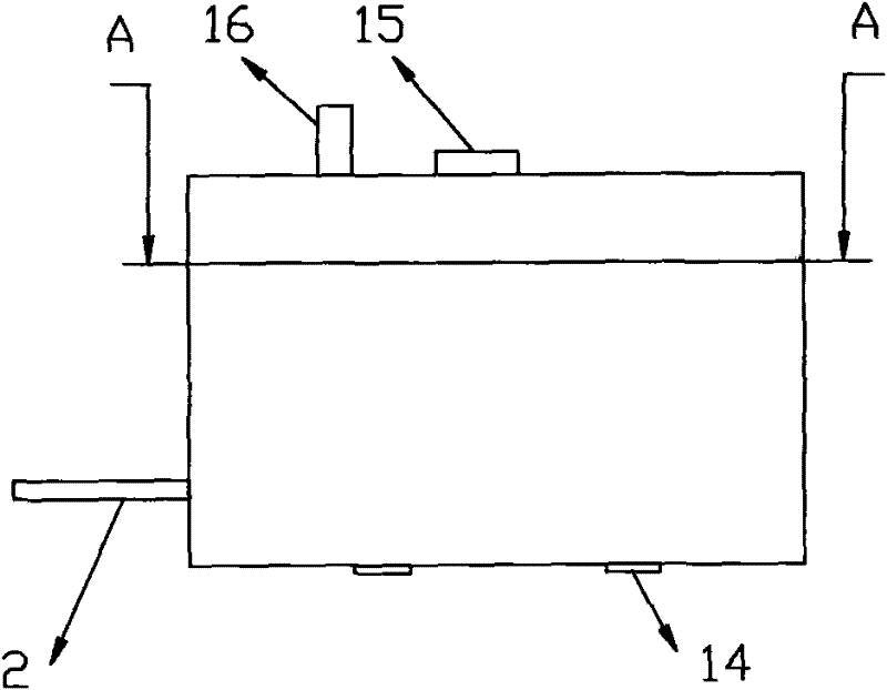
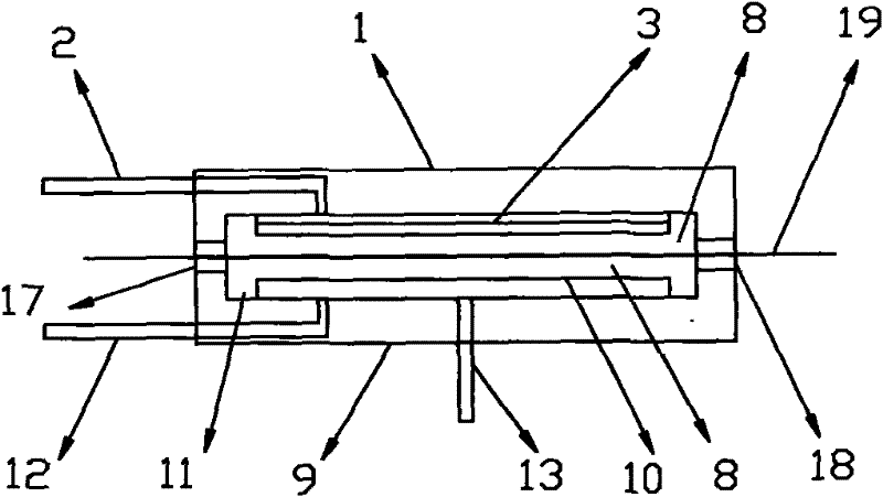
[0031] The upper steam injection orifice 3 is inclined, the connection line between the lower end 4 of the upper orifice and the upper end 5 of the upper orifice is at an angle of 15° to the horizontal plane, and the position of the condensed water tank 11 is lower than the lower steam injection orifice 10. 10mm. The upper steam injection orifice plate 3 and the lower steam injection orifice plate 10 are made of stainless steel, and the upper steam injection orifice plate 3 and the lower steam injection orifice plate 10 respectively contain 60 injection holes 6 with a diameter of 1mm-3mm. The upper part 1 of the humidifying box and the lower part 9 of the humidifying box are connected on one side by a hinge 14, and the other side of the upper part 1 of the humidifying box also includes a handle 15 for easy opening and closing. A temperature detection device 16 is also installed in the ribbon running chamber 7, and is connected with a flow meter or a regulating valve on the ste...

Embodiment 2

[0034]The upper steam injection orifice 3 is arched, the connection line between the lower end 4 of the upper orifice and the upper end 5 of the upper orifice is at an angle of 30° to the horizontal plane, and the position of the condensate water tank 11 is lower than the lower steam injection orifice 10. 25mm. The upper steam injection orifice plate 3 and the lower steam injection orifice plate 10 are made of stainless steel, and the upper steam injection orifice plate 3 and the lower steam injection orifice plate 10 respectively contain 100 injection holes 6 with a diameter of 1mm-3mm. The upper part 1 of the humidification box and the lower part 9 of the humidification box of the humidification device contain insulation layers to ensure the stability of the steam temperature; holes or hardware parts for easy installation are reserved on the shell of the humidification device. The steam chamber 8 is also equipped with a temperature detection device 16, which is connected wit...

Embodiment 3

[0037] The upper steam injection orifice 3 is inclined, the connection line between the lower end 4 of the upper orifice and the upper end 5 of the upper orifice is at an angle of 45° to the horizontal plane, and the position of the condensed water tank 11 is lower than the lower steam injection orifice 10. 50mm. The upper steam injection orifice plate 3 and the lower steam injection orifice plate 10 respectively contain 200 injection holes 6 with a diameter of 1mm-3mm. The upper part 1 of the humidifying box and the lower part 9 of the humidifying box are connected on one side by a hinge 14, and the other side of the upper part 1 of the humidifying box may also include a handle 15 for easy opening and closing. The upper part 1 of the humidification box and the lower part 9 of the humidification box of the humidification device contain insulation layers to ensure the stability of the steam temperature; holes or hardware parts for easy installation are reserved on the casing of...


PUM


Abstract

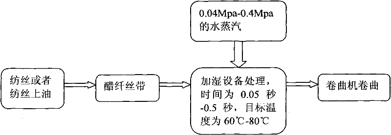
The invention provides a humidifying method of acetate fibre and a humidifying device of the acetate fibre. The humidifying device is additionally arranged before an acetate fibre ribbon is fed to a crimper for crimping operation in a production line, and the acetate fibre ribbon is humidified and warmed. Water vapour of which the pressure is 0.02-0.8Mpa is introduced into the humidifying device; the time of the acetate fibre ribbon passing through the humidifying device is 0.05-0.5 seconds, and the processed target temperature is 50-95 DEG C. The humidifying device is of a box structure and contains an upper part of a humidifying box, a lower part of the humidifying box, a ribbon operation chamber and a vapour chamber; an upper vapour jet orifice plate on the upper part of the humidifying box is inclined or arch-shaped; the position of a condensed water tank at the lower part of the humidifying box is lower than the vapour jet orifice plate; and the upper vapour jet orifice plate and the lower vapour jet orifice plate respectively comprise jet orifices, and a temperature detection device is also arranged in the ribbon operation chamber. According to the humidifying device of the acetate fibre disclosed by the invention, the strength of the acetate fibre ribbon is improved, the damage of the crimper to the ribbon is reduced, the flying of the ribbon is reduced, simultaneously the content of acetone in the ribbon is decreased, and subsequent processing load is lowered.

Description

technical field [0001] The invention relates to a production method and production equipment of acetate fiber, especially a humidification method and humidification equipment before the acetate ribbon enters into a crimping machine for crimping operation. Background technique [0002] The production process of cellulose diacetate tow (or cellulose acetate ribbon) for tobacco belongs to dry spinning, and the fiber ribbon after spinning or spinning and oiling is directly sent to the crimping machine for crimping, and finally drying. to make. The process of ribbon crimping is the process of friction and damage to the ribbon by the pressing plate and counter roller of the crimping machine. The strength of acetate fiber is low, and some monofilaments are easy to break or damage during crimping, resulting in flying flowers, which will adversely affect the production environment. [0003] A method for producing cellulose acetate disclosed in the specification of application patent...

Claims


Application Information

Patent Timeline
IPC IPC(8): D06B1/08D06B23/00
Inventor 杨占平黄建新高春红赵从涛陆书明
Owner NANTONG CELLULOSE FIBERS CO LTD
Learn More