
Device for simulating ground source heat pump

A technology of ground source heat pump and simulation device, which is applied in the direction of material thermal development to achieve the effect of complex and simplified geological structure

Inactive Publication Date: 2012-09-19
SHANGHAI SUNRISE CHEMISTRY CO LTD
View PDF5 Cites 15 Cited by
  • Summary
  • Abstract
  • Description
  • Claims
  • Application Information

AI Technical Summary

Problems solved by technology

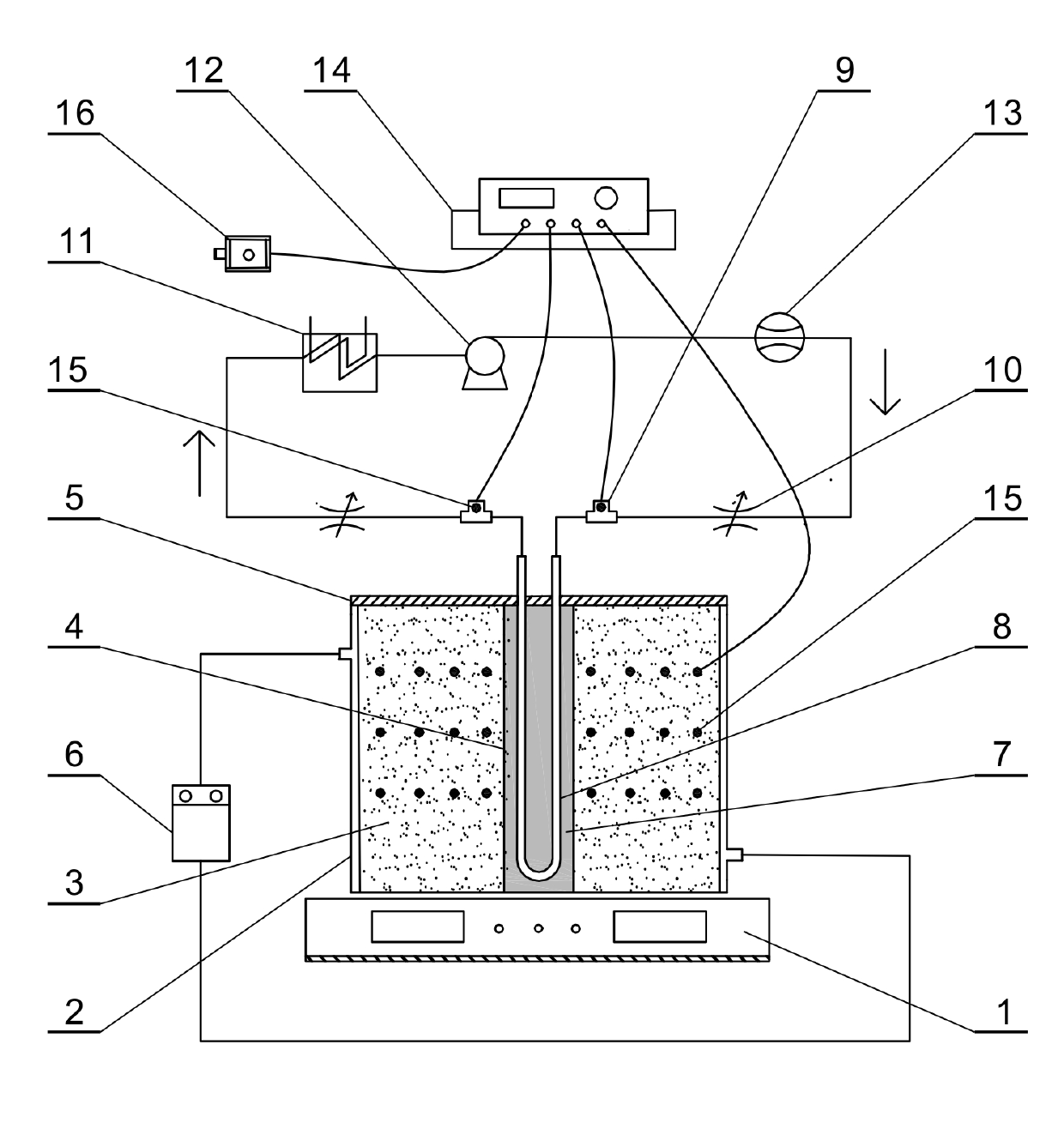
[0004] The purpose of the present invention is to provide a ground source heat pump simulation device for the lack of accurate and reasonable simulation of the ground source heat pump system in the existing technology. Research on heat pump technology provides a feasible technical solution

Method used


Image

  • Device for simulating ground source heat pump
  • Device for simulating ground source heat pump
  • Device for simulating ground source heat pump

Examples


Embodiment 1

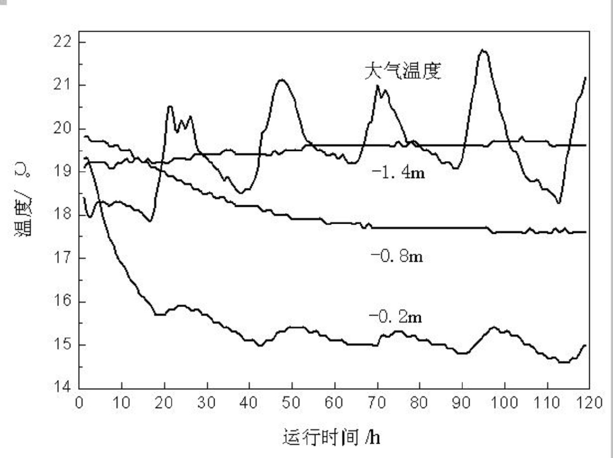
[0033] Refer to image 3 Using the present invention, under cooling conditions (the circulating water temperature is set to 0°C, and the flow rate is 3.3 L / min), the variation law of soil layer temperature at different depths with operating time is studied.

[0034] It can be seen from the figure that the surface soil (-0.2m) is most significantly affected by the heat exchange tubes and the outside world. The soil temperature drops sharply in the first 20 hours, and then changes little, and shows a phenomenon that fluctuates with atmospheric temperature fluctuations. . The figure shows that the temperature change of the surface soil lags behind the temperature change by 2 to 3 hours. As the soil depth increases, the drop in soil temperature decreases. After reaching the heat transfer equilibrium, the -0.8m temperature layer appears to be a stable state. For the bottom -1.4m soil, the average temperature is almost not affected by the heat exchange tube.

[0035] It can be seen th...

Embodiment 2

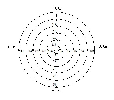
[0037] Refer to Figure 4 Using the present invention, under refrigerating conditions (the circulating water temperature is set to 0°C, and the flow rate is 3.3L / min), the variation law of different radial soil temperatures with operating time is studied.

[0038] The 0.195m soil layer in the radial direction closest to the heat exchange tube dropped sharply in the initial 20h, and later showed fluctuations and delays with the fluctuation of atmospheric temperature. The temperature of the middle two radial layers (0.335m, 0.470m) decreases slowly with the extension of running time, and tends to stabilize in the later stage. The 0.610m radial soil layer is the farthest away from the heat exchange tube, and with the effect of the polyurethane insulation material, it only shows its own heat storage and environment-dependent effects.

[0039] It can be seen that different radial soil layers have varying degrees of delay and attenuation with changes in atmospheric temperature; the close...

Embodiment 3

[0041] Using the present invention, under heating conditions (circulating water at 40°C, flow rate of 3.7L / min), run for 168h, and calculate the heat exchange model in the borehole according to the heat exchange results. The brief calculation process and results are as follows:

[0042] 1) One-dimensional heat conduction model in the borehole:

[0043] Thermal resistance term Calculated value (K·m / W) The proportion Thermal resistance from fluid to PE pipe0.013 7.39% PE pipe thermal resistance0.054 31.75% Grout thermal resistance0.104 60.86%

[0044] The thermal resistance calculation results of each part are shown in the table above. The total thermal resistance in the borehole is the sum of the three, which is 0.170 K·m / W. The thermal resistance of the grouting material accounts for the main part of the thermal resistance in the borehole, which also proves the importance of studying grouting materials. Estimate the borehole wall temperature T according to the temperature o...


PUM

PropertyMeasurementUnit
volumeaaaaaaaaaa
diameteraaaaaaaaaa

Abstract

The invention discloses a device for simulating a ground source heat pump. The device comprises a ground layer simulating system, a heat exchanger simulating system and a data collecting system, wherein the ground layer simulating system is composed of a weighbridge, a stainless steel sleeve, soil, a drill hole, a cover board and a constant-temperature water bath kettle; the heat exchanger simulating system is composed of backfill material, an U-shaped pipe, a low-temperature constant-temperature groove, a self-absorption clean water pump, a flowmeter, a tee and a valve; the data collecting system is composed of a temperature / humidity recorder, a PT100-type thermal resistor and a temperature / humidity transducer; the backfill material of the heat exchanger simulating system is arranged in the drill hole of the ground layer simulating system; and the PT100-type thermal resistor of the data collecting system is arranged in the soil of the ground layer simulating system. According to the invention, the device can be used for researching temperature distribution with different depths and different radial soil layers under the action of a buried-pipe heat exchanger and further investigating a heat exchange pattern in the soil so as to realize calculation and verification of a heat transferring model; furthermore, the device can be used for investigating the influence of different backfill materials to the total heat exchange effect and realizing screening and estimation on the backfill materials; in addition, the device also can be used for the research on the influence and the like of different circular water flows to heat exchange quantity in cold or hot working conditions.

Description

Technical field [0001] The invention relates to a vertical buried pipe ground source heat pump simulation device, in particular to the simulation of the heat exchange process among circulating water, backfill material and soil in a ground source heat pump system. Background technique [0002] The ground source heat pump system is a green and environmentally friendly air conditioning technology that uses shallow geothermal resources for heating, cooling and hot water supply. It includes buried pipe ground source heat pumps, surface water ground source heat pumps and ground water ground source heat pumps. The buried pipe ground source heat pump system that uses soil as the cold and heat source is mainly composed of the buried pipe heat exchange system, the ground source heat pump unit and the indoor heating and air conditioning terminal system. The underground heat exchange system consists of an underground heat exchanger, a circulating water pump and a circulating pipeline filled ...

Claims


Application Information

Patent Timeline
Patent Type & Authority Applications(China)
IPC IPC(8): G01N25/20
Inventor 邹玲沈军郑柏存王伟山冯中军傅乐峰陈鑫
Owner SHANGHAI SUNRISE CHEMISTRY CO LTD
Learn More