Super junction high-voltage power device structure

A high-voltage power device and device technology, which is applied in the direction of semiconductor devices, electrical components, circuits, etc., can solve the problems of increased manufacturing cost and increased process difficulty, and achieve the effect of improving withstand voltage and reliability

Active Publication Date: 2012-09-19
XIAN LONTEN RENEWABLE ENERGY TECH
View PDF7 Cites 22 Cited by
  • Summary
  • Abstract
  • Description
  • Claims
  • Application Information

AI Technical Summary

Problems solved by technology

Therefore, in order to obtain the required withstand voltage, it is generally necessary to adjust the width, concentration or spacing of Pcolumn (or Ncolumn) to achieve the required withstand voltage of the device, which will increase the difficulty of the process and increase the manufacturing cost

Method used


Image

  • Super junction high-voltage power device structure
  • Super junction high-voltage power device structure
  • Super junction high-voltage power device structure

Examples


Embodiment

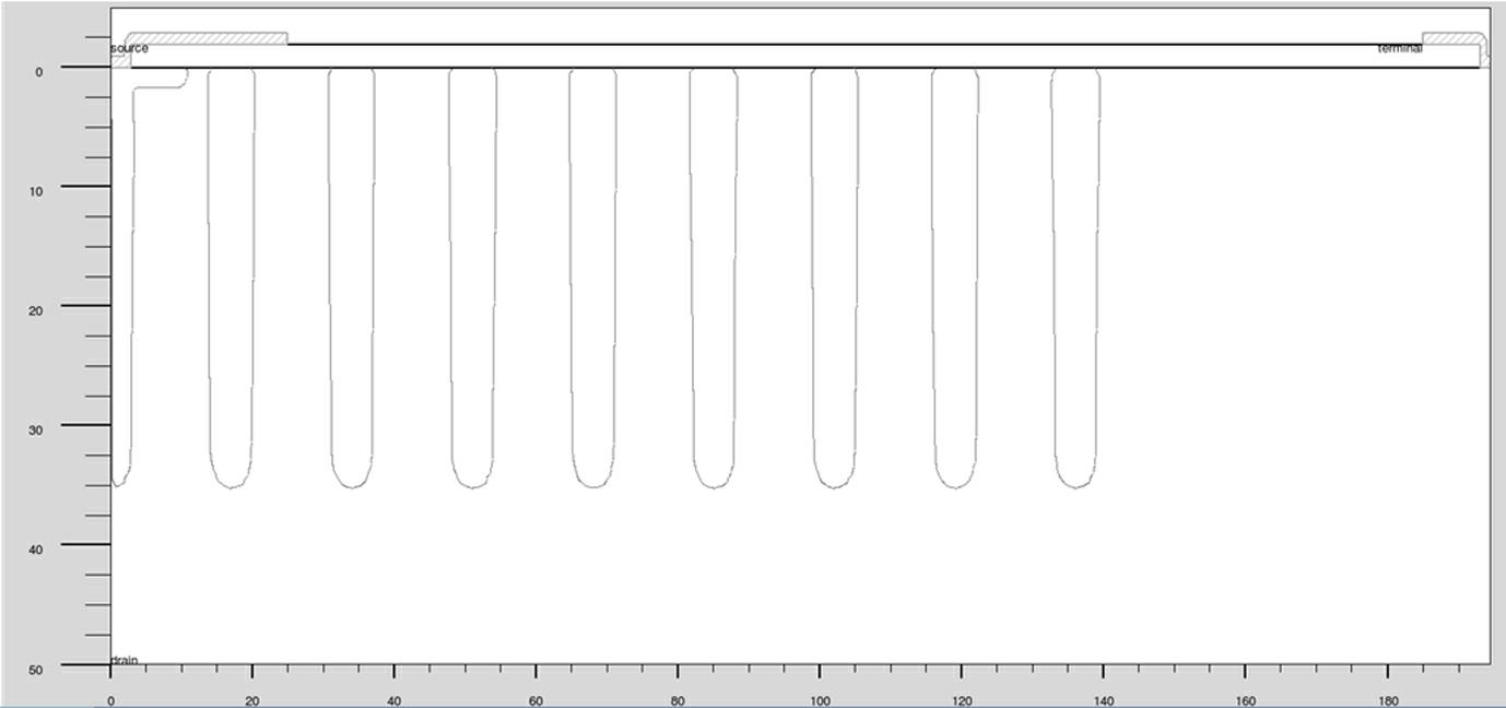
[0032] A MOSFET having a superjunction structure is illustrated, but the present invention is not limited to MOSFETs.

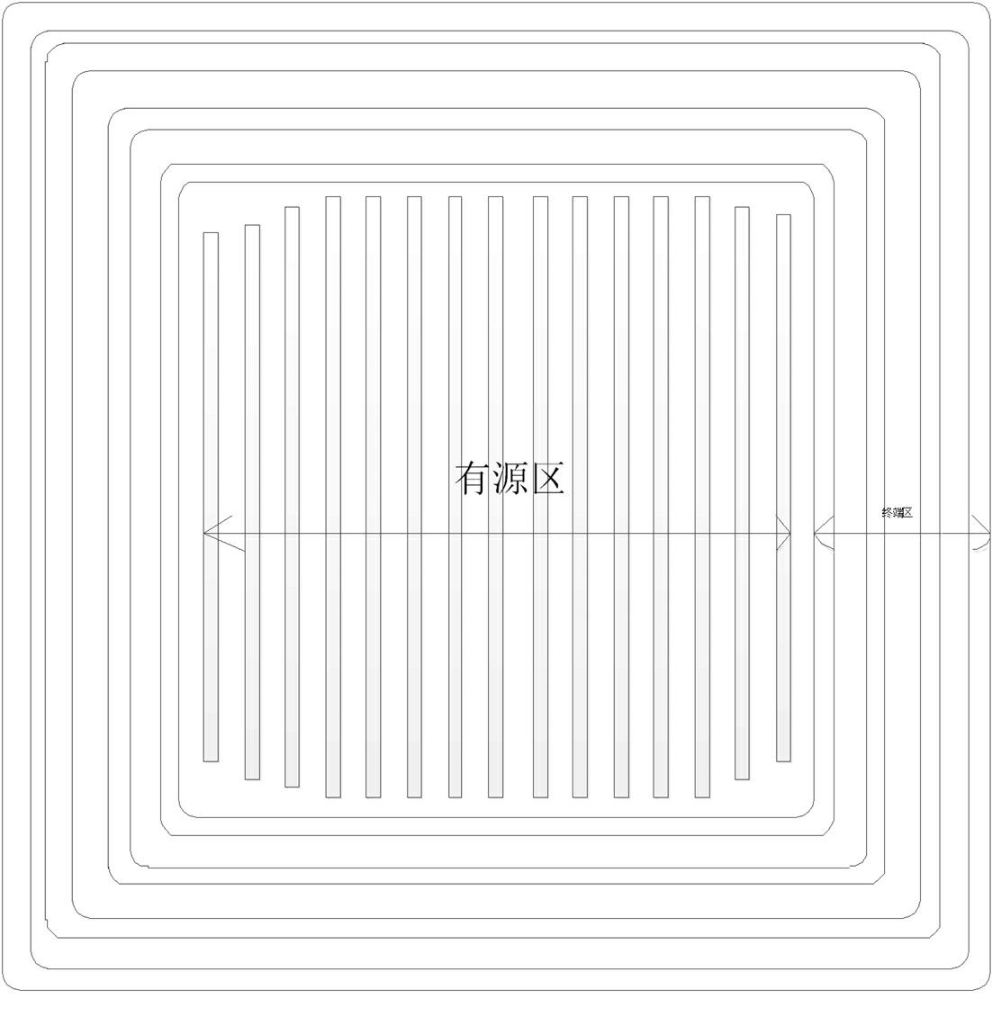
[0033] 1. Form a super junction structure on the wafer;

[0034] 2. Formation of field oxide layer;

[0035] 3. Form a gate oxide layer and form a polysilicon layer;

[0036] 4. Inject the p+ well to form a p+ ring;

[0037] 5. Form n+source region, n+ stop ring, deposit BPSG layer, and etch lead hole;

[0038] 6. Deposit the metal layer and etch.

[0039] In the present invention, the formation of the p+ ring and the p well is the same layer of photoresist, and the order described in this embodiment is not limited.

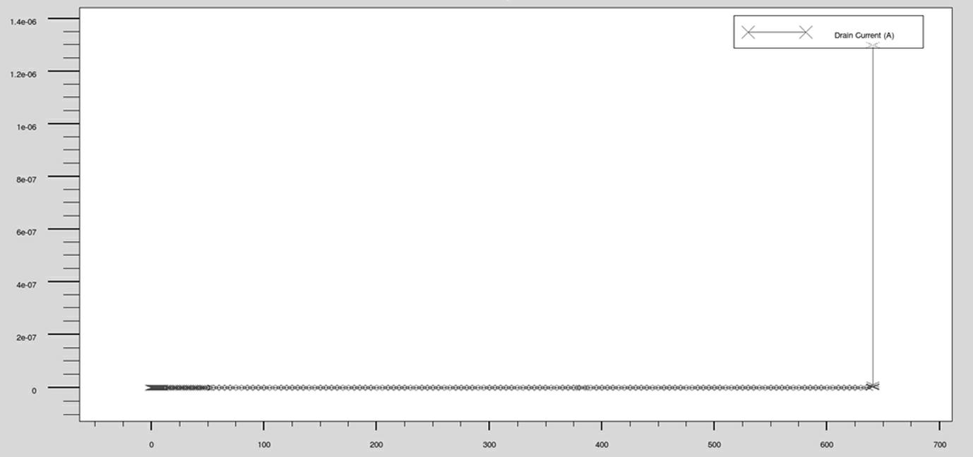
[0040] Take 700v super junction mosfet as an example:

[0041] In this example, the semiconductor of the first conductivity type is represented by an n-type semiconductor, and the semiconductor of the second conductivity type is represented by a p-type semiconductor.

[0042] The n-type substrate resistivity is 0.05ohm; the n-type epitaxia...


PUM


Abstract

The invention relates to a super junction high-voltage power device structure. A power semiconductor device many be influenced by a junction curvature effect to cause aggregation of an electric field close to a junction, so that a device is extremely easy to break down; and thus, the voltage withstanding degree of the device is required to be improved. The super junction high-voltage power device structure comprises an active region and a terminal region, wherein an epitaxial layer of a first conduction type material is arranged on a substrate layer; a composite buffer layer is formed on the epitaxial layer and comprises first semiconductor regions constituted by the first conduction type material and second semiconductor regions constituted by a second conduction type material, and the second semiconductor regions and the first semiconductor regions are arranged alternately; a well region of a second conduction type is positioned on the surface of the second semiconductor region, and is between two first semiconductor regions or between the final first semiconductor region and a cut-off ring. According to the super junction high-voltage power device structure, the withstanding voltage and the reliability of the terminal of the super junction device can be improved, so that withstanding voltage close to that of a cell region can be born by the terminal; and the structure can be realized by using the conventional super junction semiconductor manufacturing process without increasing the difficulty and the production cost of the process.

Description

technical field [0001] The invention relates to a super junction high voltage power device structure. Background technique [0002] The on-resistance Ron of the device and the breakdown voltage (breakdown voltage) of the device are important factors to measure the performance of the device. In many power semiconductor devices, high breakdown voltage and low on-resistance are required. Traditional power devices, The reverse voltage applied between the n+ substrate and the p+ well is borne by a lightly doped and thicker semiconductor layer. This layer is usually called the withstand voltage region (n-epitaxy). For high-voltage power devices, The on-resistance Ron (or on-voltage drop) is also mainly determined by the withstand voltage region (n-epitaxy). The lighter the doping of this region, or the greater the thickness, or both, the higher the breakdown voltage. With the increase of the breakdown voltage, the on-resistance increases with the power of 2.5, so the relationship...

Claims


Application Information

Patent Timeline
Patent Type & Authority Applications(China)
IPC IPC(8): H01L29/78H01L29/06
Inventor 任文珍
Owner XIAN LONTEN RENEWABLE ENERGY TECH
Why Eureka
Try Eureka