Organic electroluminescent device and preparation method of organic electroluminescent device

An electroluminescent device and luminescent technology, applied in the field of electric light sources, can solve the problems of OLED luminous efficiency, low luminous intensity, luminous efficiency and color coordinate deviation, etc., to achieve improved luminous efficiency and luminous brightness, and stable luminous performance , The effect of simple process

Active Publication Date: 2012-09-19
OCEANS KING LIGHTING SCI&TECH CO LTD +1
View PDF7 Cites 9 Cited by
  • Summary
  • Abstract
  • Description
  • Claims
  • Application Information

AI Technical Summary

Problems solved by technology

Among them, the more prominent shortcomings are that the existing OLED luminous efficiency and luminous intensity are not high, and the luminous efficiency and color coordinates shift with the increase of current density and other defects.

Method used


Image

  • Organic electroluminescent device and preparation method of organic electroluminescent device
  • Organic electroluminescent device and preparation method of organic electroluminescent device
  • Organic electroluminescent device and preparation method of organic electroluminescent device

Examples


preparation example Construction

[0040] The embodiment of the present invention also provides the preparation method of the above-mentioned organic electroluminescent device, the process flow chart of the method is as follows Figure 4 shown, see also figure 1 or figure 2 or image 3 , the method includes the following steps:

[0041] S1. Provide a transparent substrate with opposite first surface and second surface, form convex lens-type protrusions 11 distributed in an array on the first surface of the transparent substrate, and prepare a transparent substrate 1; wherein, the first surface of the transparent substrate constitutes The first surface of the light-transmitting substrate 1, and the second surface of the transparent substrate are both the second surface of the light-transmitting substrate 1;

[0042] S2. Plating an anode layer 2 on the second surface of the light-transmitting base layer 1;

[0043] S3. Coating an organic electroluminescent structure 3 on the surface of the anode layer 2 oppo...

Embodiment 1

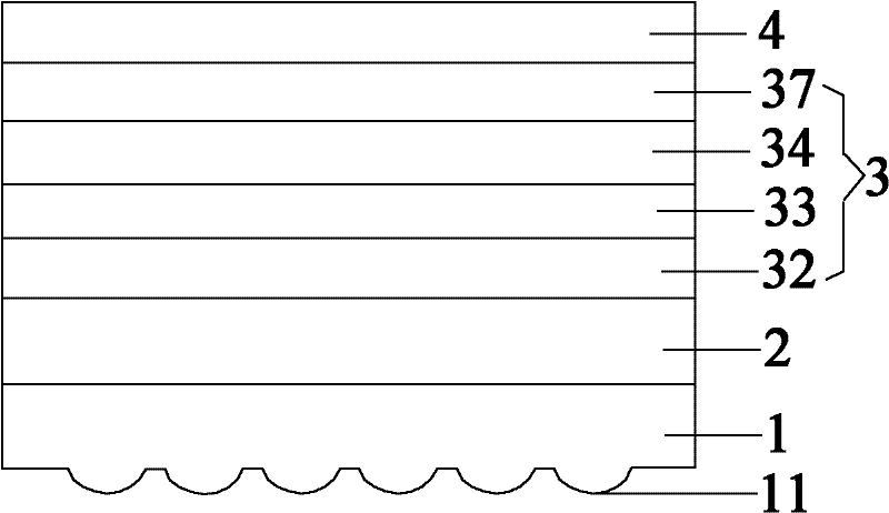
[0057] The structure of the organic electroluminescent device of this embodiment is as follows figure 1 As shown, the organic electroluminescent device includes a light-transmitting base layer 1, an anode layer 2, a hole transport layer 32, a light emitting layer 33, an exciton balance layer 34, an electron transport layer 37 and a cathode layer 4 which are sequentially stacked. Wherein, the light-transmitting base layer 1 has a first surface and a second surface opposite to each other, the first surface is provided with convex lens-shaped protrusions 11 distributed in an array, and the second surface is superposed with the anode layer 2 . The hole transport layer 32 , the light emitting layer 33 , the exciton balancing layer 34 , and the electron transport layer 37 constitute the organic electroluminescent structure 3 .

[0058] The diameter of the convex lens-shaped convex portion provided on the first surface of the light-transmitting base layer 1 is 20 μm, and the focal le...

Embodiment 2

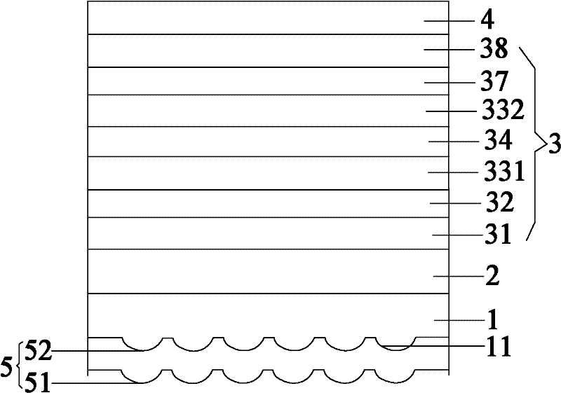
[0068] The structure of the organic electroluminescent device of this embodiment is as follows figure 2 As shown, the organic electroluminescent device includes a light-enhancing film layer 5, a light-transmitting base layer 1, an anode layer 2, a hole injection layer 31, a hole transport layer 32, a red light-emitting layer 331, and an exciton balance layer stacked in sequence. layer 34 , green light emitting layer 332 , electron transport layer 37 , electron injection layer 38 and cathode layer 4 . Wherein, one surface of the light enhancing film layer 5 is provided with concave lens-shaped concave portions 52 distributed in an array, and the other surface opposite to the surface provided with the concave portions 52 is provided with convex lens-shaped convex portions 51 distributed in an array. The surface of the organic electroluminescent device of this embodiment is used as the light-emitting surface of the organic electroluminescent device; the light-transmitting base l...


PUM

PropertyMeasurementUnit
diameteraaaaaaaaaa
lengthaaaaaaaaaa
luminanceaaaaaaaaaa

Abstract

The invention discloses an organic electroluminescent device which comprises a transparent substrate layer, an anode layer, an organic electroluminescent structure and a cathode layer sequentially superposed. The transparent substrate layer is provided with a first surface and a second surface which are opposite to each other. The first surface is provided with convex lens-type convex parts arranged in array, and the second surface and the anode layer are superposed. The organic electroluminescent structure comprises an exciton balance layer and at least a luminescent layer superposed with the exciton balance layer. The organic electroluminescent device is high in luminescent efficiency and brightness and stable in luminescent efficiency and chromaticity coordinates. The preparation method of the organic electroluminescent device is simple in process, improves the production efficiency, reduces the production cost and is appropriate for industrialized production.

Description

technical field [0001] The invention belongs to the technical field of electric light sources, and in particular relates to an organic electroluminescent device and a preparation method thereof. Background technique [0002] The electric light source industry has always been a hotspot of research by countries all over the world, and occupies a very important position in the world economy. At present, the widely used light source is gas discharge light source. The principle of this light source is to fill the inside of the lamp with a mixed gas containing mercury after vacuuming, and use gas discharge to emit light or ultraviolet light generated by gas discharge to excite phosphors to emit light. However, the pulsed flashes of gas discharge light sources can easily cause visual fatigue, and mercury pollutes the environment. With the advancement of society and technology, research and development of energy-saving and environmentally friendly green light sources to replace trad...

Claims


Application Information

Patent Timeline
Patent Type & Authority Applications(China)
IPC IPC(8): H01L51/52H01L51/50H01L51/56C09K11/06
Inventor 周明杰王平钟铁涛冯小明
Owner OCEANS KING LIGHTING SCI&TECH CO LTD
Why Eureka
Try Eureka