
On-site dynamic balance monitoring correcting device and method of high-speed rotary machinery for boat

A technology of on-site dynamic balance and correction device, which is applied in static/dynamic balance test, measuring device, machine/structural component test, etc., can solve the problems of inapplicability, complex space, limited cabin, powerlessness, etc. The effect of improving flight rate and combat effectiveness, reducing vibration and noise levels, and shortening troubleshooting time

Inactive Publication Date: 2012-09-26
中国船舶重工集团公司第七0四研究所
View PDF4 Cites 17 Cited by
  • Summary
  • Abstract
  • Description
  • Claims
  • Application Information

AI Technical Summary

Problems solved by technology

[0006] (1) For simultaneous online monitoring of multi-channel dynamic balance, the existing device is too bulky and not suitable for complex and limited space cabins;
[0007] (2) The existing dynamic balancing method has poor human-computer interaction, and often requires professionals to record the data of each trial weight of each channel monitored, and then input it into the dynamic balancing software one by one. The process is cumbersome, not intuitive, and High requirements for the professional knowledge of operators;
[0008] (3) At present, the land-use dynamic balancing method is generally used for on-site dynamic balancing of dual-plane single-axis equipment, but for the high-speed rotary mechanical equipment with many multi-speed, multi-shaft, and multi-balance planes on ships, the existing methods often seem inadequate
[0009] (4) When the hull is tilted and swayed, the existing dynamic balance method has no measures or means to correct the error generated by the tilting and swaying equipment dynamic balance monitoring

Method used


Image

  • On-site dynamic balance monitoring correcting device and method of high-speed rotary machinery for boat
  • On-site dynamic balance monitoring correcting device and method of high-speed rotary machinery for boat
  • On-site dynamic balance monitoring correcting device and method of high-speed rotary machinery for boat

Examples


Embodiment Construction

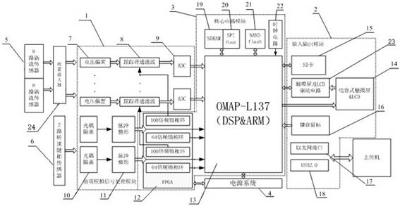
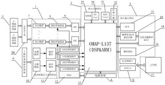
[0034] Such as figure 1 Shown is a structural schematic diagram of the on-site dynamic balance monitoring and correction device for marine high-speed gyratory machinery. The device includes an eddy current sensor 5 (preferably, it can also be a speed sensor and an acceleration sensor), a speed key phase sensor 6, a preamplifier 24, and a dynamic balance monitoring and correction circuit.

[0035] The eddy current sensor 5 is mainly responsible for collecting displacement signals required for monitoring and dynamic balance, and the key phase sensor 6 is a sensor for measuring the rotor speed and vibration phase reference. The power supply of the front-end sensor and the preliminary conditioning of the signal are completed by the preamplifier 24 .

[0036] The dynamic balance monitoring and correction circuit is mainly composed of the following modules, input and output module 2, front-end analog signal processing module 1, device core circuit module 3, and power system module 4...


PUM


Abstract

The invention relates to an on-site dynamic balance monitoring correcting device and an on-site dynamic balance monitoring correcting method of high-speed rotary machinery for a boat. Signals collected by an electricity vortex sensor and a rotating speed key phase sensor are transmitted to a dynamic balance monitoring correcting circuit through a head amplifier, the dynamic balance monitoring correcting circuit receives the signals transmitted by the head amplifier, the signals are transmitted to a front end analog signal processing module to be processed and are then transmitted to a device core circuit module to be calculated and stored, an input and output module and the device core circuit module exchange data, a power supply system module comprises a power supply processing module and a power supply voltage monitoring and resetting circuit, the power supply processing module provides power supply for each module chip, and the power supply voltage monitoring and resetting circuit receives all power supply signals and outputs warning and control signals. The vibration noise level of equipment for the boat is effectively reduced, and the failure handling time of the equipment for the boat is shortened; the dimension of a dynamic balance instrument is reduced; the environment adaptability of the dynamic balance instrument can be improved; the man-machine interaction can be realized; and the fast data collection and storage can be completed, and credible data is provided for monitoring and failure diagnosis.

Description

technical field [0001] The invention relates to a mechanical balance technology, in particular to an on-site dynamic balance monitoring and correction device and method for a marine high-speed rotary machine. Background technique [0002] At present, steam turbines, diesel engines, gas turbines, generators and other high-speed rotary machinery are the key equipment of modern ships, and their vibration levels are directly related to the stability and comfort of ships. For military ships, the vibration level of equipment is not only Affect its flight rate and combat effectiveness, and affect its own stealth. Therefore, the on-site vibration and noise reduction of the key equipment of the ship itself is very important for the stability and concealment of the modern ship. [0003] The main cause of the vibration of the rotary machine is the inertial force and inertial force of the unbalanced mass. Statistics from on-site fault diagnosis show that faults caused by unbalanced fo...

Claims


Application Information

Patent Timeline
Patent Type & Authority Applications(China)
IPC IPC(8): G01M1/38
Inventor 周璞符栋梁章艺钟焱张心玮代学昌
Owner 中国船舶重工集团公司第七0四研究所
Learn More