Micro-strip scoop-type feed slit surface wave excitation antenna

A technology for exciting antennas and feeding slots, which is applied to leaky waveguide antennas, circuits, and structural forms of radiation elements, etc., can solve problems such as increased loss, difficulty in use, and difficulty in ensuring dimensional processing accuracy, and achieve simplified design, large front-to-back ratio, small structure effect

Inactive Publication Date: 2012-09-26
吕清
View PDF0 Cites 5 Cited by
  • Summary
  • Abstract
  • Description
  • Claims
  • Application Information

AI Technical Summary

Problems solved by technology

In such a high frequency band, whether it is a metal waveguide or a traditional standard microstrip line, the proces

Method used


Image

  • Micro-strip scoop-type feed slit surface wave excitation antenna
  • Micro-strip scoop-type feed slit surface wave excitation antenna
  • Micro-strip scoop-type feed slit surface wave excitation antenna

Examples


Embodiment

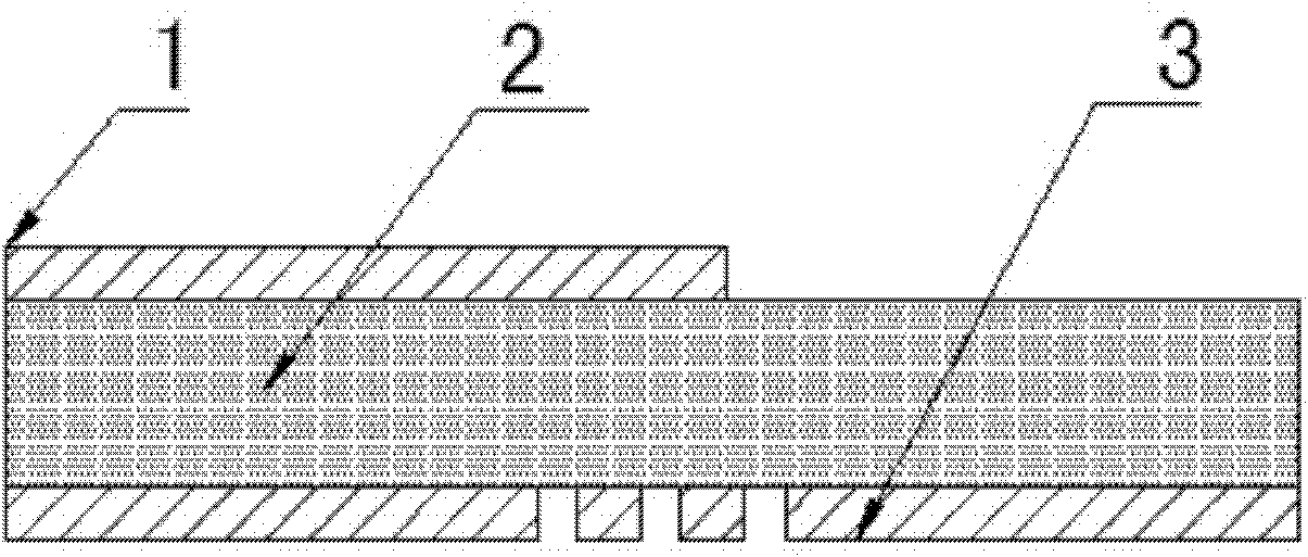
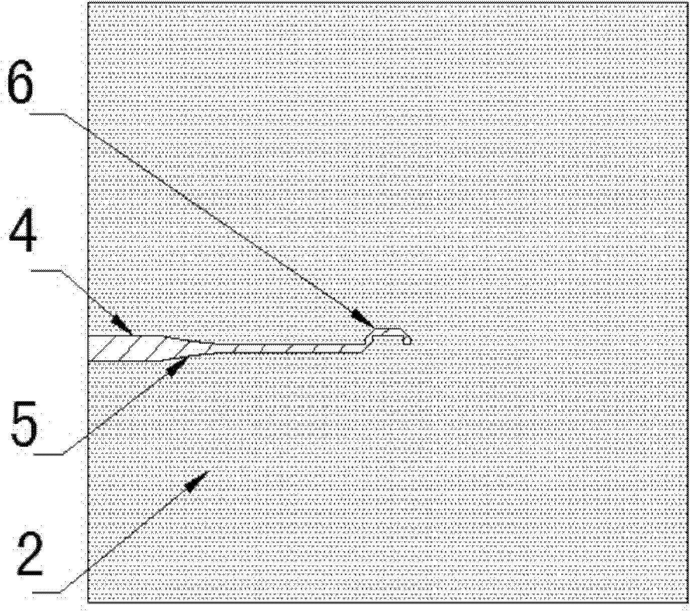
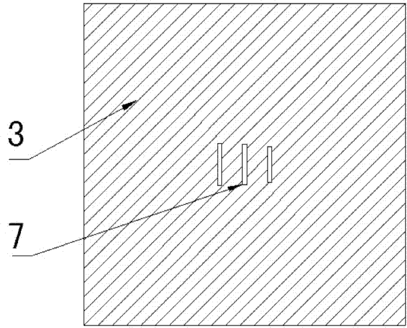
[0023] The overall structure of the surface wave excitation antenna is as follows Figure 1~3 As shown, the antenna consists of a feeding unit and a radiating unit.

[0024] The microstrip spoon-feed slot surface wave excitation antenna is divided into three layers, the upper and lower layers are metal layers 1 and 3, the middle is the dielectric layer 2, the upper metal layer 1 is the microstrip feeding structure of the antenna, and the microstrip feeding unit It consists of a 50Ω first microstrip line 4 connected to a spoon-shaped microstrip 6 through an exponential gradient microstrip structure 5. The signal is excited and starts from the 50Ω first microstrip line 4. Impedance matching is realized through an exponential gradient microstrip structure 5. The spoon-shaped The microstrip 6 feeds power to the radiating unit 7 of the rear metal layer, wherein the radiating unit 7 is provided with three Yagi slits in the grounded metal layer 3 to realize directional radiation.

...


PUM


Abstract

The invention discloses a micro-strip scoop-type feed slit surface wave excitation antenna. The antenna is characterized in that: the surface wave excitation antenna contains a feed unit and a radiation unit; the surface wave excitation antenna is divided into three layers, and an upper layer and a lower layer are metal layers (1) and (3), and a middle part is a dielectric layer (2); the upper metal layer (1) is a micro-strip feed structure of the antenna; a micro-strip feed unit is formed by connection between a 50 omega first micro-strip line (4) and a scoop-type micro-strip (6) through an index gradient micro-strip structure (5); starting from the 50 omega first micro-strip line (4), an excitation signal realizes impedance matching through the index gradient micro-strip structure (5); the scoop-type micro-strip (6) carries out feed on a radiation unit (7) of a rear metal layer, wherein the radiation unit (7) sets three yagi slits in a grounding metal layer (3) so as to realize directed radiation.

Description

technical field [0001] The invention relates to a microstrip spoon-shaped feeding slot surface wave excitation antenna, which belongs to the field of antennas in radio equipment. Background technique [0002] At present, microwave technology is rapidly developing in the millimeter wave band, and countries all over the world are actively developing millimeter wave components and systems. In such a high frequency band, whether it is a metal waveguide or a traditional standard microstrip line, the processing accuracy is difficult to guarantee because the size is too small, and the loss is increased to an unusable level. Therefore, an important problem facing the electronic system in the millimeter wave band is how to effectively transmit signals to the devices in it. The surface wave transmission system is widely used in the millimeter wave band because of its good transmission characteristics and low loss in the high frequency band. Commonly used structures include dielectri...

Claims


Application Information

Patent Timeline
IPC IPC(8): H01Q13/28H01Q1/38
Inventor 吕清颜慧李悬雷陈方园
Owner 吕清
Why Eureka
Try Eureka