
Miniaturized intelligent signal suppressor

A suppressor and signal technology, which is applied in the direction of communication interference, electrical components, transmission systems, etc., can solve the problems of increasing equipment costs, not being able to shield 3G mobile phone signals, and high power consumption, so as to reduce radiation, cover a wide frequency band, The effect of radiation is small

Active Publication Date: 2012-09-26
CHENGDU JIUHUA YUANTONG TECH DEV
View PDF4 Cites 3 Cited by
  • Summary
  • Abstract
  • Description
  • Claims
  • Application Information

AI Technical Summary

Problems solved by technology

With the development of science and technology, people's requirements for electronic products are becoming more and more stringent, and the demand for miniaturization of electronic products is also increasing. At present, the signal suppressors (jammers, jammers) produced at home and abroad, the The functions are relatively single, either they can only shield GSM mobile phone signals, but cannot shield the current 3G mobile phone signals, or they do not involve the shielding of walkie-talkie signals, or they cannot shield the current digital cheating devices
If it is necessary to suppress and shield the above three signals at the same time, multiple signal suppressors are required to work at the same time, which greatly increases the cost of the equipment, and requires a large amount of manpower to serve the signal suppression work. At the same time, it also increases the difficulty for users to carry , the user needs to carry multiple signal suppressors at the same time, which is extremely inconvenient to carry and use, and the existing signal suppressors have signal backflow, signal interference, self-excitation of voltage-controlled oscillators, high power consumption, and strong radiation, which are harmful to the human body more serious damage

Method used


Image

  • Miniaturized intelligent signal suppressor
  • Miniaturized intelligent signal suppressor

Examples


Embodiment Construction

[0015] The technical solution of the present invention will be further described in detail below in conjunction with the accompanying drawings, but the protection scope of the present invention is not limited to the following description.

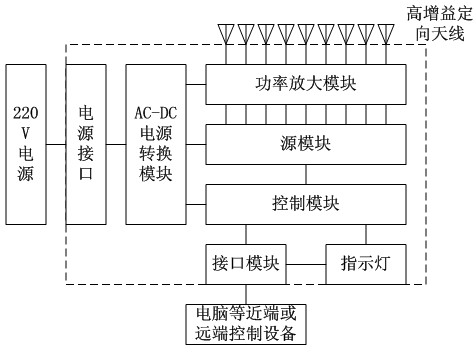
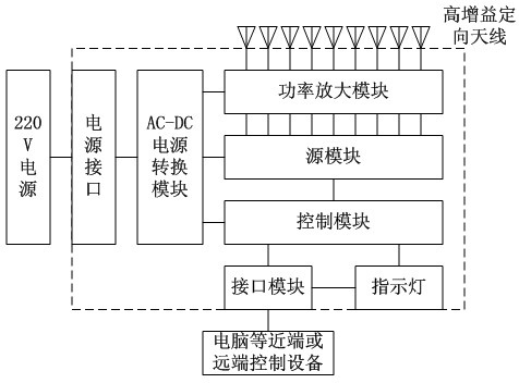
[0016] like figure 1 As shown, the miniaturized intelligent signal suppressor includes a casing and a core circuit placed in the casing, the core circuit includes a power amplifier module, a source module and a control module, and the casing is provided with one or more An antenna, one or more interface modules and one or more indicator lights, the external control device is connected to the interface module, the interface module is connected to the indicator light and the control module, the control module, the source module, the power amplifier module and the antenna are connected in sequence, The source module is composed of at least nine relatively independent voltage-controlled oscillators. Each voltage-controlled oscillator generates ...


PUM


Abstract

The invention discloses a miniaturized intelligent signal suppressor which comprises a shell and a core circuit. The core circuit comprises a power amplifying module, a source module and a control module. The shell is provided with one or a plurality of antennae, one or a plurality of interface modules, and one or a plurality of indicating lamps. An external control device is connected with the interface modules. The interface modules are connected with the indicating lamps and the control module. The control module is connected with the source module, the power amplifying module and the antennae sequentially. The source module is composed of at least nine independent voltage-controlled oscillators. The miniaturized intelligent signal suppressor combines shielding of all cellphone models, shielding of interphones and shielding of digital cheater together, is miniaturized, small in size, and convenient to carry. Requirement of miniaturization of the signal suppressor is met. Radiating grooves reserved outside the suppressor guarantees fast radiation. By matching a small signal processing circuit with a high-gain directional antenna, environmental protection, energy conservation, emission reduction, and radiation reduction are achieved.

Description

technical field [0001] The invention relates to a miniaturized intelligent signal suppressor. Background technique [0002] With the continuous development of communication technology, wireless signal suppressors have been widely used in many places, such as various examination rooms, school classrooms, churches, courts, libraries, confidential conference centers (rooms), theaters, hospital wards, government, Finance, prisons, public security, military sites and other places where the use of mobile phones is prohibited. With the development of science and technology, people's requirements for electronic products are becoming more and more stringent, and the demand for miniaturization of electronic products is also increasing. At present, the signal suppressors (jammers, jammers) produced at home and abroad, the The functions are relatively single, either they can only shield GSM mobile phone signals, but cannot shield the current 3G mobile phone signals, or they do not invo...

Claims


Application Information

Patent Timeline
Patent Type & Authority Applications(China)
IPC IPC(8): H04B1/00H04K3/00
Inventor 宁涛王文林张涛马剑青王兴斌吴伟冬孙建华
Owner CHENGDU JIUHUA YUANTONG TECH DEV
Learn More