Use of specific composite materials as extinguishing material for electric arcing in electric apparatuses

A composite material and electrical equipment technology, applied in electrical components, circuits, electrical switches, etc., can solve the problems of complex arc extinguishing technology

Inactive Publication Date: 2012-09-26
SCHNEIDER ELECTRIC ENERGY FRANCE
View PDF4 Cites 3 Cited by
  • Summary
  • Abstract
  • Description
  • Claims
  • Application Information

AI Technical Summary

Problems solved by technology

However such arc extinguishing techniques are complex to implement as they require vacuum bottles to be placed in series in the chamber containing the arcing contacts

Method used


Image

  • Use of specific composite materials as extinguishing material for electric arcing in electric apparatuses
  • Use of specific composite materials as extinguishing material for electric arcing in electric apparatuses
  • Use of specific composite materials as extinguishing material for electric arcing in electric apparatuses

Examples


Embodiment Construction

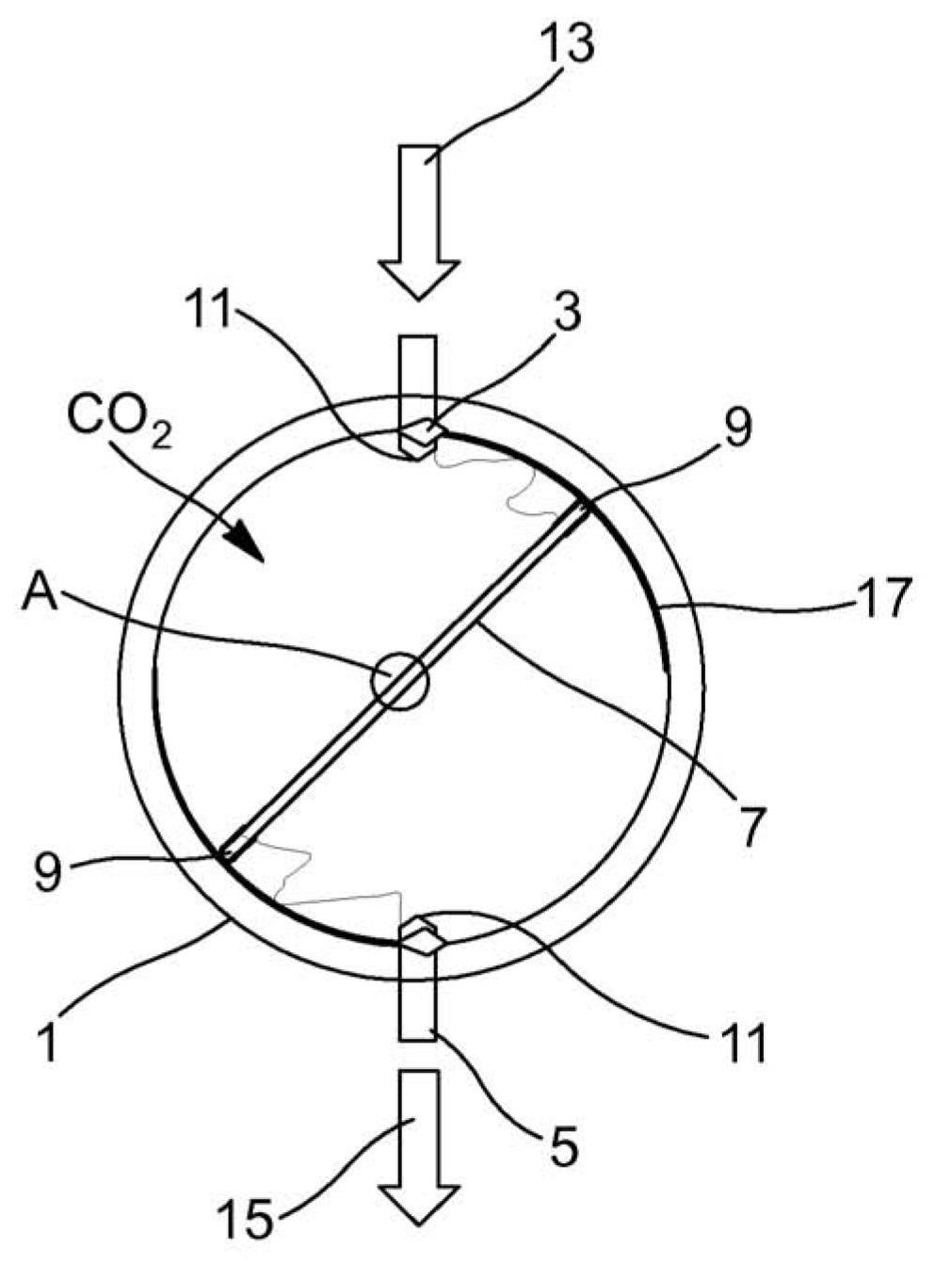
[0052] figure 1 An insulating chamber 1 is shown with two diametrically opposed stationary contacts 3, 5 at its edges and containing a moving contact 7 mounted concentrically with the insulating chamber 1 about an axis A in the center.

[0053] The moving contact 7 is in the form of a rod, its length is slightly shorter than the inner diameter of the insulating cavity 1, and has an end 9 that can be in contact with the ends 11 of the static contacts 3, 5 at the same time, and the static contacts 3, 5 penetrate into the interior of the insulating cavity 1 .

[0054] The input current is indicated by a first arrow 13 at the first fixed contact 3 ; the output current is indicated by a second arrow 15 away from the other fixed contact 5 diametrically opposite to the first fixed contact.

[0055] washer( figure 1 not shown in ) around the end 11 of each static contact 3,5; it is formed from a composite material according to the invention, ie comprising a polymer matrix (advantage...


PUM


Abstract

The present invention relates to the use of a composite material including a polymer matrix and at least one metal fluoride charge selected from among cerium fluorides CeF3 and / or CeF4, lanthanum fluoride LaF3, magnesium fluoride MgF2, barium fluoride BaF2 or mixtures of same, as extinguishing material for electric arcing in an electric apparatus.

Description

technical field [0001] The present invention relates to a composite material for electric arc extinction comprising a polymer matrix, which may be a fluorinated polymer matrix, and specific metal fluoride fillers. [0002] These materials can be applied in electrical equipment where arcing may occur, such as switchgear, for example a medium or high voltage switch or a medium or high voltage switch disconnector. [0003] The general field of the invention is therefore that of electric arcs and means of extinguishing electric arcs. Background technique [0004] An electric arc is a visible electrical current, usually in an insulating medium, that occurs between two conductive surfaces that are close to each other, provided that a sufficient potential difference exists between the two surfaces. [0005] The current is generally evidenced by the ionization of the insulating medium through which the current passes, and thus precisely constitutes a plasma which may reach high tem...

Claims


Application Information

Patent Timeline
Patent Type & Authority Applications(China)
IPC IPC(8): H01H9/30H01H1/22H01H33/78
CPCH01H33/78H01H1/22H01H9/302
Inventor D.皮科兹
Owner SCHNEIDER ELECTRIC ENERGY FRANCE
Why Eureka
Try Eureka