
Construction equipment of hole drilling/punching cast-in-place pile with self-provided mud pit and mud separating device

A technology of mud separation and construction equipment, which is applied in the direction of sheet pile walls, foundation structure engineering, construction, etc., to achieve the effects of strong rock-socketing ability, easy control of construction costs, and low cost of pile foundations

Inactive Publication Date: 2012-10-03
徐守田
View PDF6 Cites 17 Cited by
  • Summary
  • Abstract
  • Description
  • Claims
  • Application Information

AI Technical Summary

Problems solved by technology

[0006] The present invention proposes a construction equipment and construction method for drilling / punching cast-in-situ piles with a mud pool and a mud separation device, and its purpose is to overcome the above-mentioned deficiencies in the existing pile foundation construction technology under adverse geological conditions , improve the construction equipment and technology, add impact hammer, mud separation and collection equipment on the basis of the equipment and technology of positive (reverse) circulation bored piles, and realize the recycling of mud, which has the advantages of construction safety, high work efficiency, high quality, and easy construction. The process is easy to operate and the construction cost is easy to control, etc.

Method used


Image

  • Construction equipment of hole drilling/punching cast-in-place pile with self-provided mud pit and mud separating device
  • Construction equipment of hole drilling/punching cast-in-place pile with self-provided mud pit and mud separating device
  • Construction equipment of hole drilling/punching cast-in-place pile with self-provided mud pit and mud separating device

Examples


example

[0031] Project name: Lianyungang Youth Pioneer Building Lianyungang Kuge Real Estate Development Co., Ltd.

[0032] Project Location: Intersection of Huanghai Avenue and Huaguoshan Avenue in Lianyungang

[0033] Project overview: The building is 100 meters high, the pile is about 50 meters long, 160 bored and punched cast-in-place piles are designed, the end of the pile is 50 cm of medium weathered gneiss, the upper part of the pile foundation is 14-16 meters of silt, and 12 -16 meters, the lower part of the silt is 20 meters, the construction site has no hardening treatment, and the self-contained mud drilling (punching) mechanical equipment and methods are used for construction. First make 4 test piles, complete in 4 days, one pile per day, the bearing capacity of a single pile is 9600KN, the maximum sinking amount after static load field test is within 20mm, which belongs to end piles, and each pile driver for engineering pile construction is greater than One, after the en...


PUM


Abstract

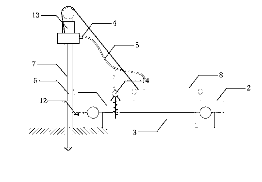
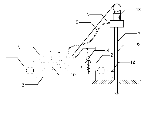
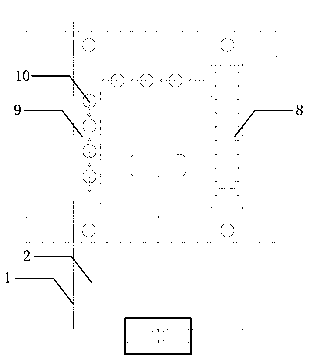
The invention discloses construction equipment of a hole drilling / punching cast-in-place pile with a self-provided mud pit and a mud separating device, which consists of the self-provided mud pit, the mud separating device, normal / reverse circulation drilling / punching drilling machine and a caterpillar pile driver platform, and adopts the construction method that the mud pit is arranged on the caterpillar pile driver platform, the drilling machine simultaneously drills and removes sediments through a sediment removing pipe, and the mud is absorbed into a screen mud conveyor through a mud pipe to be preliminarily separated with the bigger clay particles being separated out; the separated mud flows into a mud separating tank, and the sediments sink into the extrusion mud separator to be removed; the liquid mud flows into the self-provided mud pit of the pile driver through a mud overflow hole and is injected into the pile hole for cyclic utilization through a mud flowrate control valve. The invention has the advantages that the mud pit is not required to be excavated on the construction site, so as to avoid the on-site mud contamination; the mud is filtered layer by layer with the clay particles and sediments being separated out for cyclic utilization; the mud concentration is controllable, the hole is regularly formed, and the hole forming is quick in speed; and the rock embedding performance is high, the bearing capability is high after the pile is driven, and the pile foundation is low in cost.

Description

technical field [0001] The invention relates to a construction equipment and a construction method for drilling / punching cast-in-place piles with its own mud pool and mud separation device, and belongs to the technical field of building construction. Background technique [0002] With the development of the national economy, all kinds of civil and industrial buildings are increasingly high-rise, and cast-in-place piles have been recognized by many design units and construction units for their unique advantages of large bearing capacity. It is indeed an affordable form of foundation. [0003] Affected by factors such as building structure type, load distribution, geological conditions, construction equipment and construction conditions, the choice of pile type is greatly limited, especially when encountering high groundwater levels such as silt or silt soil or quicksand layers. In the case of unfavorable geological conditions, according to the current dry and wet methods of ...

Claims


Application Information

Patent Timeline
IPC IPC(8): E21B21/01E02D5/34
Inventor 徐守田
Owner 徐守田
Learn More