
Infrared temperature measuring device based on ultrasound ranging temperature compensation

A technology of infrared temperature measurement and temperature compensation, which is applied in measuring devices, optical radiation measurement, radiation pyrometry, etc., to achieve the effects of saving costs, ensuring safety and convenience, and shortening measurement time

Inactive Publication Date: 2012-10-03
SHANGHAI UNIVERSITY OF ELECTRIC POWER
View PDF3 Cites 31 Cited by
  • Summary
  • Abstract
  • Description
  • Claims
  • Application Information

AI Technical Summary

Problems solved by technology

[0004] The present invention is to provide an infrared temperature measuring device based on ultrasonic distance measurement and temperature compensation. The device can not only solve the technical problem of real-time monitoring, but also aim at the infrared temperature measurement process. There is an error in the distance of the point to be measured. Ultrasonic ranging technology is used to obtain the distance from the measured object to the infrared thermometer online. According to the online measurement result, the temperature value measured by the thermometer is compensated or corrected to eliminate The additional error brought by the temperature measurement distance improves the accuracy of temperature measurement, and combines the infrared thermometer with precise positioning technology to realize online monitoring of multi-point temperature in space and save costs

Method used


Image

  • Infrared temperature measuring device based on ultrasound ranging temperature compensation
  • Infrared temperature measuring device based on ultrasound ranging temperature compensation
  • Infrared temperature measuring device based on ultrasound ranging temperature compensation

Examples


Embodiment Construction

[0014] The present invention will be further described below in conjunction with the accompanying drawings and embodiments.

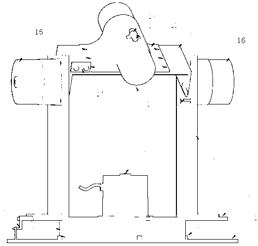
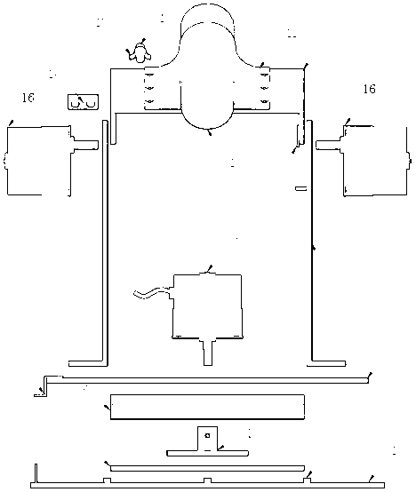
[0015] Such as Figure 1 to Figure 3 As shown, the infrared temperature measuring device based on ultrasonic ranging temperature compensation of the present invention includes CPU, horizontal and vertical stepping motors 8, 16, infrared temperature measuring unit, ultrasonic ranging module, wireless communication interface, calibration parameter storage Module, control system and calibration module, system positioning interface circuit, mechanical structure of the gimbal, etc.

[0016] Horizontal and vertical stepping motors 8, 16, infrared temperature measurement unit, ultrasonic distance measuring module, laser pointer 12, positioning switch 9 are installed on the mechanical structure of the cloud platform, and the mechanical structure of the cloud platform communicates with the control system through the laser pointer 12 Connected with the calibrati...


PUM


Abstract

The invention relates to an infrared temperature measuring device based on the ultrasound ranging temperature compensation. Stepping motors in horizontal direction and vertical direction, an infrared temperature measuring unit, an ultrasound ranging module, a laser indicator and a positioning switch are arranged on a holder mechanical structure; the holder mechanical structure is connected with a calibrating module through the laser indicator and a control module; a calibrated parameter storing module, a control system and calibrating module, a system positioning interface circuit and the ultrasound ranging module are respectively connected with a central processing unit (CPU); the infrared temperature measuring unit sends the detected temperature value signal to the CPU, CPU sends the value signal to an upper computer through a wireless communication interface module. The infrared temperature measuring device can perform non-contact online temperature measurement on the to-be-tested points distributed at every position of the space; the infrared temperature measuring device is high in precision and quick in measuring speed; the structure design is reasonable, the infrared thermometer and the accurate positioning technology are combined, therefore, the online monitoring of multi-point temperature of the space is realized, and the cost is saved.

Description

technical field [0001] The invention relates to an infrared temperature measuring device in electric power equipment, in particular to an infrared temperature measuring device for non-contact online ultrasonic distance measurement and temperature compensation. Background technique [0002] Temperature is a physical quantity that indicates the intensity of molecular motion inside an object, and is one of the important parameters to determine the state of matter of an object. In the power system, most electrical equipments operate under the condition of high voltage and high current. In many power outage accidents, power outages and maintenance often occur due to local overheating of equipment. This not only affects the safe operation of the equipment and threatens public safety, but also brings significant economic losses to the power supply side. If early warning and quick measures can be taken in the early stage of the accident, it will be able to effectively avoid the occ...

Claims


Application Information

Patent Timeline
IPC IPC(8): G01J5/00G01J5/02
Inventor 朱武桂媛崔昊杨汤乃云张华富马维亚
Owner SHANGHAI UNIVERSITY OF ELECTRIC POWER
Learn More