Superconducting wire component and preparation method thereof

A technology of superconducting wires and components, applied in superconducting devices, superconducting/high-conducting conductors, usage of superconducting elements, etc. Burning and other problems, to achieve the effect of simple structure, smooth surface and low cost

Inactive Publication Date: 2012-10-03
INNOVA SUPERCONDUCTOR TECH
View PDF5 Cites 12 Cited by
  • Summary
  • Abstract
  • Description
  • Claims
  • Application Information

AI Technical Summary

Problems solved by technology

[0003] During the application of bismuth-based high-temperature superconducting materials, if a certain part of the wire is bent or broken, one or more superconducting cores here will lose their current-carrying capacity, while the remaining cores of the wire will lose their current carrying capacity. If the total current exceeds the current carrying capacity of these cores, the excess part will be shunted by the silver or silver alloy matrix, but the silver or silver alloy matrix may not be able to withstand the large shunt current in the wire. Cause the wire jacket to burn, thereby disconnecting the wire, or even catching fire, endangering the entire superconducting device
In addition, the critical current (Ic) of a single bismuth-based superconducting tape at 77K is already very high, but it is still difficult to meet the requirements of some large superconducting devices, such as large superconducting transformers, superconducting motors, superconducting cables, Superconducting energy storage devices and current leads, etc. These superconducting devices usually need to pass a large current, and the current value is greater than the critical current of a single superconducting strip
The Chinese patent with application number 200510070732.9 provides a superconducting wire assembly, which connects multiple superconducting wires together, and wraps the outer surface with at least one layer of metal coating whose mechanical strength is higher than that of a single superconducting wire , although this component can improve the current and mechanical strength, it still cannot meet the requirements of some large superconducting devices

Method used


Image

  • Superconducting wire component and preparation method thereof
  • Superconducting wire component and preparation method thereof
  • Superconducting wire component and preparation method thereof

Examples


Embodiment 1

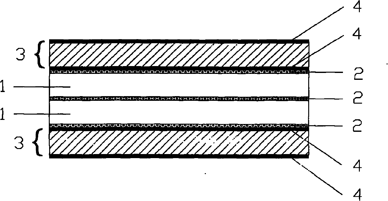
[0044] Such as Figure 9 , figure 1 and Figure 10 As shown, two bismuth-based high-temperature superconducting wires 1 are selected, and the two superconducting wires 1 are respectively coiled on the pay-off reel 8, and then two metal reinforcement tapes 3 are selected, and the two metal reinforcement tapes 3 are respectively coiled On the pay-off reel 8. Place the four wire-coiled pay-off reels 8 on the bracket 7 perpendicular to the base 6, and the order of placement is metal reinforcement tape 3 pay-off reel 8, superconducting wire 1 pay-off reel 8, Superconducting wire 1 pay-off reel 8, metal reinforcement tape 3 pay-off reel 8. The width surfaces of the heads of these four wires are brought together from top to bottom in order, and go around the same guide wheel 10, and then pass through the heating tank 12 at a speed of 1.0m / min for heating, and the heating temperature is 200°C , apply 1kg pressing force to the heating plate 14 above the uppermost metal reinforcemen...

Embodiment 2

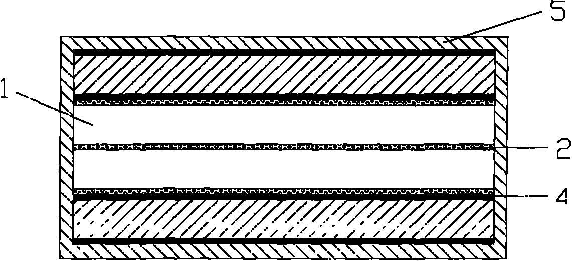
[0047] Such as Figure 9 and figure 2 As shown, two bismuth-based high-temperature superconducting wires 1 are selected, and the two superconducting wires 1 are respectively coiled on the pay-off reel 8, and then two metal reinforcement tapes 3 are selected, and the two metal reinforcement tapes 3 are respectively coiled On the pay-off reel 8. Place the four wire-coiled pay-off reels 8 on the bracket 7 perpendicular to the base 6, and the order of placement is metal reinforcement tape 3 pay-off reel 8, superconducting wire 1 pay-off reel 8, Superconducting wire 1 pay-off reel 8, metal reinforcement tape 3 pay-off reel 8. Put the width surfaces of the four wire heads together from top to bottom in order, and bypass the same guide wheel 10, and then pass through the heating tank 12 at a speed of 1.5m / min for heating, and the heating temperature is 250°C , apply 100kg pressing force to the heating plate 14 above the uppermost metal reinforcement strip 3 in the heating tank 12...

Embodiment 3

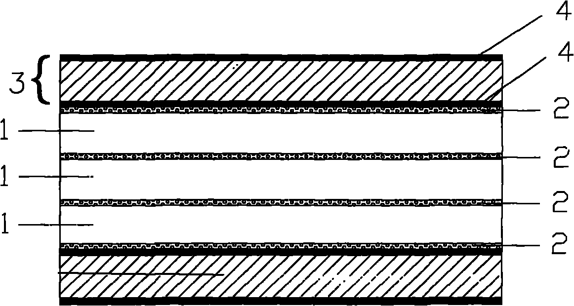
[0050] When the superconducting wire assembly 11 is composed of three superconducting wires 1 and two metal reinforcing strips 3, Figure 9 A pay-off reel 8 needs to be added on the bracket 7 on the left side, on which the superconducting wire 1 is coiled.

[0051] Such as Figure 9 and image 3 As shown, three bismuth-based high-temperature superconducting wires 1 are selected, and these three superconducting wires 1 are respectively coiled on the pay-off reel 8, and then two metal reinforcement tapes 3 are selected, and these two metal reinforcement tapes 3 are respectively coiled on the discharge reel 8. 8 on the reel. Place the five pay-off reels 8 that have been coiled on the support 7 perpendicular to the base 6, and the order of placement is metal reinforcement tape 3 pay-off reel 8, superconducting wire 1 pay-off reel 8, Superconducting wire 1 pay-off reel 8, superconducting wire 1 pay-off reel 8, metal reinforcement tape 3 pay-off reel 8. The width surfaces of the...


PUM

PropertyMeasurementUnit
thicknessaaaaaaaaaa
thicknessaaaaaaaaaa
tensile stressaaaaaaaaaa

Abstract

The invention relates to a bismuth-series high-temperature superconducting wire component and a preparation method thereof. The superconducting wire component comprises at least two single superconducting wires with superconductivity, the width surfaces among the single superconducting wires are parallelly connected together in an electrical contact manner, and at least one metal reinforcing band is parallelly connected on the outer width surface of each of the two outermost superconducting wires in parallel connection. In order to further improve mechanical strength of the superconducting wire component, at least one metal coating with the mechanical strength higher than that of single metal reinforcing band is coated on the outer surface of the superconducting wire component. The superconducting wire component prepared by the method is high in mechanical strength and critical current.

Description

technical field [0001] The invention relates to a superconducting wire assembly, in particular to a high-temperature superconducting wire assembly prepared by using a bismuth-based high-temperature superconducting material and a metal reinforcing tape and a preparation method thereof. Background technique [0002] Bismuth-based high-temperature superconducting tape is currently the only high-temperature superconducting material that can be produced on a large scale. Superconducting cables, superconducting motors, superconducting current limiters, and superconducting magnetic separators made of bismuth-based high-temperature superconducting tapes are used. Major breakthroughs have been made in the research and development of products such as superconducting maglev trains and superconducting energy storage systems, and many projects have entered the stage of prototype trial operation. Bismuth-based high-temperature superconducting strips are made by Powder-In-Tube (PIT) method...

Claims


Application Information

Patent Timeline
Patent Type & Authority Applications(China)
IPC IPC(8): H01B12/02H01B13/00
CPCY02E40/641Y02E40/60
Inventor 孙海波
Owner INNOVA SUPERCONDUCTOR TECH
Why Eureka
Try Eureka