All-plastic optical fiber radio broadcast communication system and implementation method thereof

A technology of plastic optical fiber and wireless broadcasting, which is applied in optical fiber radio, optical fiber transmission, data exchange details, etc. It can solve the problems of easy penetration into the human body through the skin, impossibility of user troubleshooting, and reduction of the overall life of the system to achieve safety. And the effects of enhanced maintainability, improved equipment utilization efficiency, and high data throughput

Inactive Publication Date: 2015-04-22
杨帆
View PDF5 Cites 0 Cited by
  • Summary
  • Abstract
  • Description
  • Claims
  • Application Information

AI Technical Summary

Problems solved by technology

And the setting of the optical amplifier increases the complexity of the product, greatly improves the energy consumption, and also reduces the overall life of the system
In addition, the splicing and laying of SMF-28 standard optical fibers require professional equipment and technical personnel, which is very inconvenient
The optical transmission band used is invisible light. When the laser emits high power, it will cause permanent damage to the retina.
The optical fiber itself is also potentially dangerous. It is easy to penetrate the skin and enter the human body, and it is difficult to distinguish and take it out. It is necessary to take corresponding protective measures during operation.
Therefore, as a commercial solution, a dedicated team is required for construction and maintenance. It is almost impossible for users to troubleshoot by themselves, and the overall cost of system ownership and operation and maintenance is relatively high.

Method used


Image

  • All-plastic optical fiber radio broadcast communication system and implementation method thereof
  • All-plastic optical fiber radio broadcast communication system and implementation method thereof
  • All-plastic optical fiber radio broadcast communication system and implementation method thereof

Examples


Embodiment

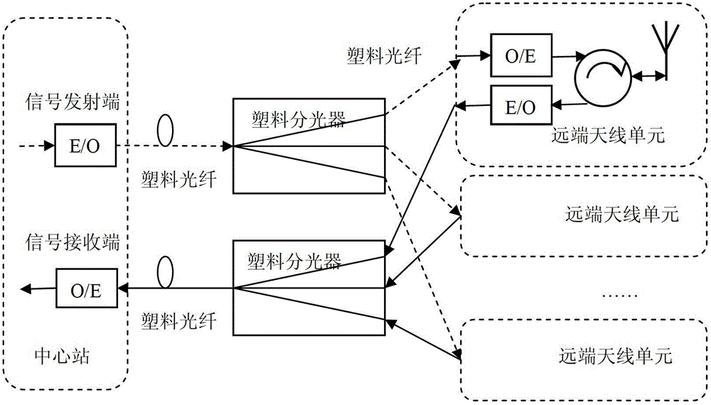
[0047] The structure diagram of this embodiment is as figure 1 As shown, the system is divided into two parts: the central routing station (referred to as the central station) and the remote antenna unit (referred to as the antenna unit). The central station and one or more antenna units are connected through plastic optical fiber and plastic passive optical splitter. Connections can use a variety of topologies including tree and star. The communication principle and structure of the uplink and downlink are the same. Among them, the central station provides centralized signal processing services, and is responsible for connecting and communicating with the signal source of the upper link.

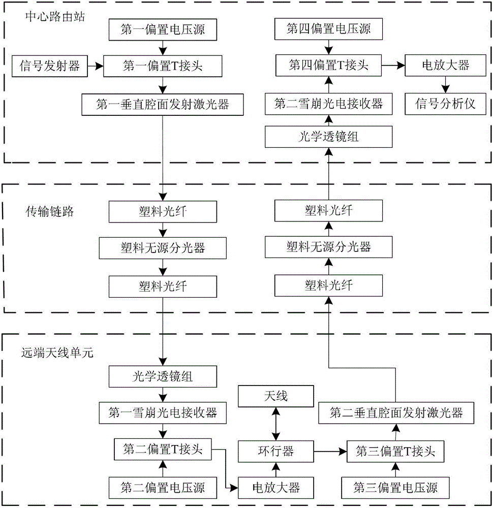
[0048] Such as figure 2 As shown, the central routing station includes a signal transmitting end (in the experiment, a signal generator that can generate IEEE standard radio signals is used to replace the demonstration), and a signal receiving end (in the experiment, a signal analysis d...


PUM


Abstract

The invention discloses an all-plastic optical fiber radio broadcast communication system and an implementation method thereof. The system comprises a central route station and one or more remote antenna units, wherein a plastic passive optical splitter is arranged between the central route station and a remote antenna, the central route station is connected with the passive optical splitter through a plastic optical fiber, and one or more remote antenna units are connected with the plastic passive optical splitter through the plastic optical fiber. According to the invention, by adopting a vertical-cavity surface-emitting laser in a red light waveband, and utilizing amplification effect of a light transmission window for the plastic optical fiber and a plastic passive light split machine, and a snow slide photoelectric receiver, vices of large loss and large dispersion of a medium are overcome, the short-distance, high-quality and safe radio frequency signal transmission is realized, and compatibility of different communication and broadcast standards is ensured by utilizing transparence of an optical fiber about a protocol. In addition, according to the invention, a system framework is greatly simplified, the integrated cost of a product is reduced, and the utilization efficiency of the device is improved.

Description

technical field [0001] The invention relates to the technical field of wireless broadcast communication, in particular to a low-cost all-plastic optical fiber wireless broadcast communication system and its implementation method. Background technique [0002] With social development and technological progress, the public has increasingly urgent and strong demands for information broadcasting and interaction, hoping to communicate and share anytime, anywhere. Therefore, the next-generation wireless broadcast communication technology will be forced to adapt to the rapidly expanding data traffic and provide ubiquitous high-quality access services. At present, it is difficult for broadcast / telecom operators to keep up with this trend and complete wireless coverage in remote or complex environments at a relatively low cost. With the advancement of technology, the combination of low-cost optical fiber transmission and high-cost wireless transmission will become a new trend. As a...

Claims


Application Information

Patent Timeline
Patent Type & Authority Patents(China)
IPC IPC(8): H04B10/2575H04B10/2581H04B10/69H04L12/18
Inventor 杨帆
Owner 杨帆
Why Eureka
Try Eureka