Chemical waste liquid disposal system

A technology for disposal system and waste liquid, applied in waste heat treatment, furnace, lighting and heating equipment, etc., can solve the problems of high energy consumption, low investment, easy leakage of harmful substances, etc. stable effect

Active Publication Date: 2014-01-08
ANHUI CONCH GRP +2
View PDF1 Cites 1 Cited by
  • Summary
  • Abstract
  • Description
  • Claims
  • Application Information

AI Technical Summary

Problems solved by technology

[0006] 1. Safe landfill method: low investment and simple operation, but there are great consequences. Hazardous substances are easy to leak and cause environmental pollution. Once the lining system fails, it will cause long-term and continuous threats to the surrounding environment and the public, and landfill The farm occupies a large amount of land, resulting in waste of land resources;
[0007] 2. High-temperature incineration method and pyrolysis method: the general principle of hazardous waste reduction, recycling and harmless treatment that meets the technical policy requirements of hazardous waste pollution prevention and control. The volume of treated hazardous waste residues can be reduced by 90%, and the weight It can be reduced by 80%, but the initial investment cost is high, the operation cost and operation technology are difficult, and the high-temperature incineration method often needs to use auxiliary fuel, which consumes a lot of energy; the pyrolysis method currently does not have a large processing capacity and is suitable for Limited range, need classification preprocessing
Environmental protection issues, resource issues and sustainable development issues have increasingly become one of the most important factors restricting social and economic development. Many disadvantages of first developing the economy and then solving environmental protection and resource issues have become increasingly apparent and are becoming more and more serious. The result will inevitably lead to Without economic development, environmental problems cannot be solved well, let alone sustainable economic development.

Method used


Image

  • Chemical waste liquid disposal system
  • Chemical waste liquid disposal system
  • Chemical waste liquid disposal system

Examples


Embodiment Construction

[0032] The specific implementation of the present invention will be described in further detail below by describing the embodiments with reference to the accompanying drawings, so as to help those skilled in the art have a more complete, accurate and in-depth understanding of the inventive concepts and technical solutions of the present invention.

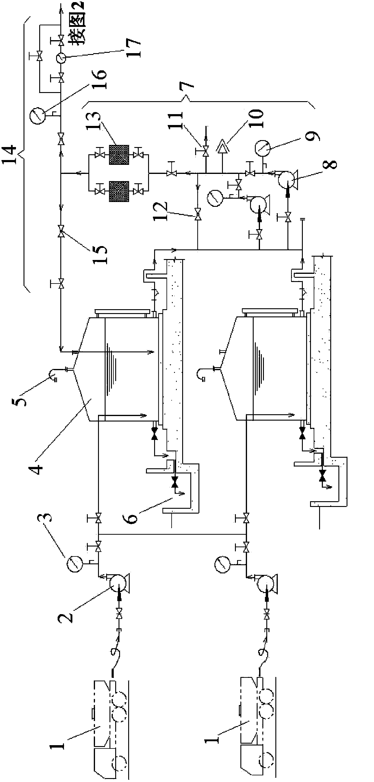
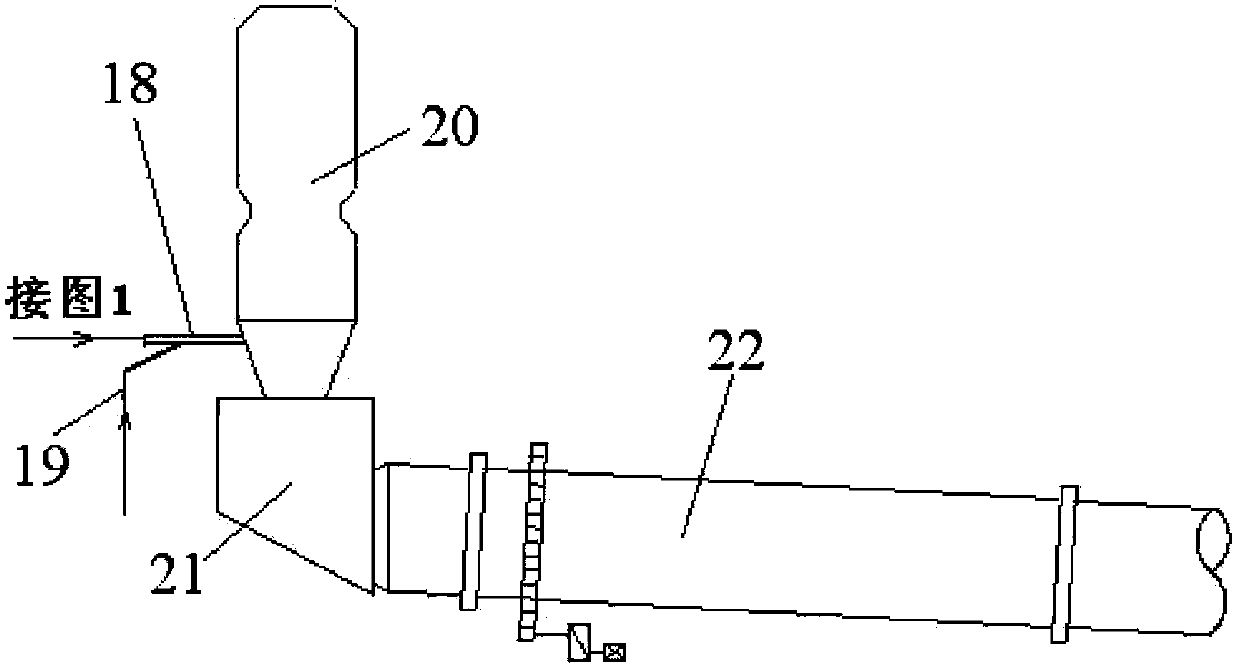
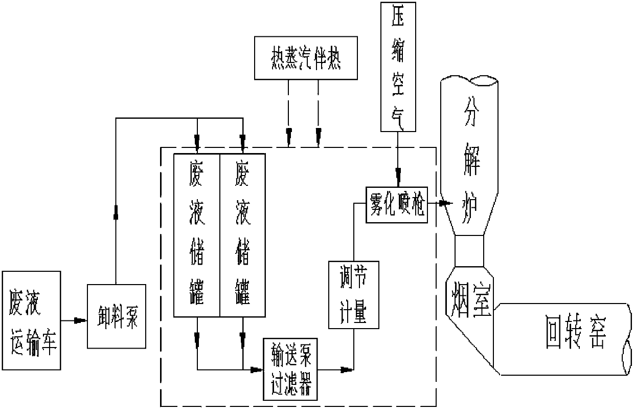
[0033] Such as figure 1 and figure 2 The structure of the present invention shown is a chemical waste liquid treatment system, which is provided with a waste liquid storage tank 4 .

[0034] In order to solve the problems existing in the prior art and overcome its defects, and to realize the purpose of the invention of the harmless treatment of chemical waste liquid by using a new type of cement firing system, the technical scheme adopted by the present invention is:

[0035] Such as figure 1 and figure 2 As shown, the chemical waste liquid treatment system provided by the present invention is also provided with a conveying an...


PUM


Abstract

The invention discloses a chemical waste liquid disposal system which is provided with a conveying and filtering system (7), an adjusting and measuring system (14) and an atomizing and spraying device (18); and the chemical waste liquid disposal system is connected with a pre-calcining kiln system of a cement new dry-process kiln through the atomizing and spraying device (18). With the adoption of the technical scheme, the chemical waste liquid disposal system has the beneficial effects that the technical characteristics of a cement firing system are fully utilized, chemical waste liquid is subjected to full and efficient innocent treatment, generated gas and ash are directly treated by utilizing the cement new dry-process kiln, no waste discharge exists, no complicated waste gas and waste slag treatment facility is required to be additionally arranged, and meanwhile, heat contained in the waste liquid is also completely utilized to achieve the purpose of carrying out innocent, resource and one hundred percent reduction on the waste liquid.

Description

technical field [0001] The invention belongs to the technical field of combining the production of building materials and the disposal of hazardous waste in chemical production. Specifically, the invention relates to a chemical waste liquid treatment system. Background technique [0002] With the development of modern industry and the improvement of people's living standards, the amount of hazardous waste is increasing year by year. [0003] Hazardous waste has many types and complex components, and is toxic, corrosive, flammable and explosive, and its pollution is latent and lagging. It is one of the key and difficult issues in global environmental protection. Hazardous waste pollution has been listed as a serious worldwide problem, which poses a great threat to human survival just like the destruction of the ozone layer, the greenhouse effect, population explosion, and energy crisis. [0004] Existing hazardous waste treatment technology: At present, many countries in th...

Claims


Application Information

Patent Timeline
Patent Type & Authority Patents(China)
IPC IPC(8): C04B7/43F27D17/00
Inventor 轩红钟杨旺生汪克春张长乐盛赵宝程竹松
Owner ANHUI CONCH GRP
Why Eureka
Try Eureka