Waste gas incinerator
An incinerator and waste gas technology, applied in incinerators, combustion methods, combustion types, etc., can solve the problems of high equipment cost, low cost performance, waste of materials, etc., and achieve the effect of reducing equipment cost, consumption, and diameter.
- Summary
- Abstract
- Description
- Claims
- Application Information
AI Technical Summary
Problems solved by technology
Method used
Image

Examples
Embodiment Construction
[0016] The present invention is described in further detail now in conjunction with accompanying drawing. These drawings are all simplified schematic diagrams, which only illustrate the basic structure of the present invention in a schematic manner, so they only show the configurations related to the present invention.
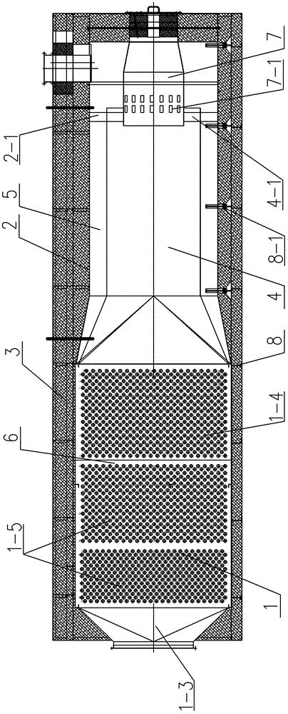
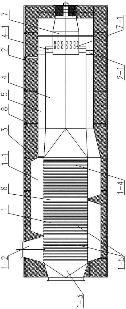
[0017] Such as figure 1 , figure 2 The best embodiment of the exhaust gas incinerator of the present invention shown, it comprises preheater 1 and furnace shell 2, the shell of preheater 1 communicates with furnace shell 2, the shell of preheater 1 and furnace shell 2 The exterior is covered with a heat insulation layer 3. The preheater 1 has a column tube and a turning air chamber 1-1. The shell of the preheater 1 is connected with a waste gas inlet 1-2 and an air outlet 1-3. The furnace shell 2 is equipped with There is an exhaust gas combustion chamber 4, and the exhaust gas inlet 1-2 sequentially passes through the tube-side channel composed of tube col...
PUM
 Abstract
Description
Claims
Application Information
 - R&D
- Intellectual Property
- Life Sciences
- Materials
- Tech Scout
- Unparalleled Data Quality
- Higher Quality Content
- 60% Fewer Hallucinations
Browse by: Latest US Patents, China's latest patents, Technical Efficacy Thesaurus, Application Domain, Technology Topic, Popular Technical Reports.
© 2025 PatSnap. All rights reserved.Legal|Privacy policy|Modern Slavery Act Transparency Statement|Sitemap|About US| Contact US: help@patsnap.com