Energy-saving control method for heating furnace hydraulic system

A hydraulic system, energy-saving control technology, applied in the direction of furnace control devices, lighting and heating equipment, furnaces, etc., can solve the problems of high investment, difficult to control oil temperature, high energy consumption, etc., achieve simple control methods, reduce energy consumption, The effect of improving reliability

Active Publication Date: 2012-10-10
鞍钢集团工程技术有限公司
View PDF6 Cites 4 Cited by
  • Summary
  • Abstract
  • Description
  • Claims
  • Application Information

AI Technical Summary

Problems solved by technology

The disadvantages of this structural form are that the circulating filtration, cooling and heating of the hydraulic oil are not sufficient, the anti-pollution level of the oil cannot be guaranteed, and the oil temperature is also difficult to control. Larger cooler and cooling water volume and more filter groups occupy a large area and require a higher investment, which also brings about heat generation in the hydraulic system and reduced service life of hydraulic components
The disadvantage of this structural form is that the main oil supply pump and the circulating oil pump perform their respective functions independently. Generally, the operation time of furnace replacement is 10-15 minutes, and the intermittent time of furnace replacement is 45-50 minutes. It still keeps working continuously and consumes a lot of energy. The accumulator in the circuit of the main oil supply pump only plays the role of protecting the oil pressure in the oil circuit and does not have the function of pressure output.

Method used


Image

  • Energy-saving control method for heating furnace hydraulic system
  • Energy-saving control method for heating furnace hydraulic system
  • Energy-saving control method for heating furnace hydraulic system

Examples


Embodiment Construction

[0022] The specific embodiment of the present invention will be further described below in conjunction with accompanying drawing:

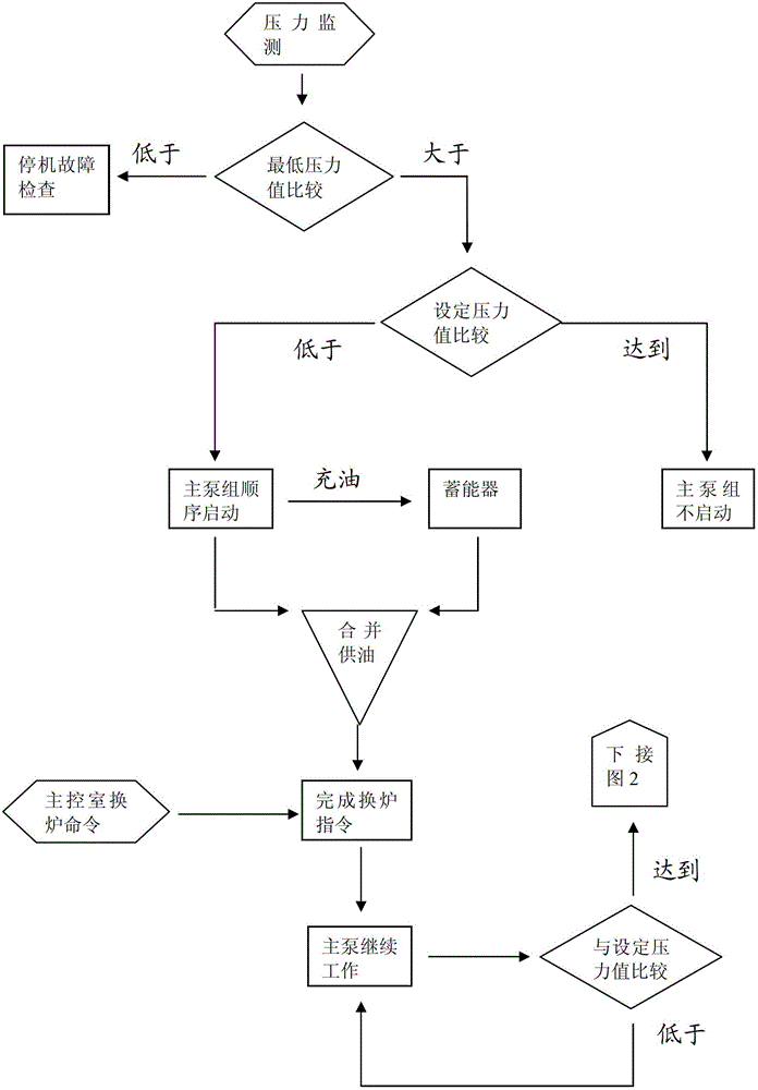
[0023] In the energy-saving control process of the heating furnace hydraulic system in the present invention, the circulating pump group and the main pump group are alternately operated, and the accumulator is involved in the hydraulic power output of the furnace replacement operation, so that the circulating pump group and the main pump group have Part of the time is in sleep and energy-saving state, and the specific control steps are as follows:

[0024] 1) see figure 1 , before the furnace replacement operation, the pressure status of the hydraulic system is monitored in real time online. When the system pressure is higher than the set value, the main pump unit does not start and is in a dormant state; when the system pressure is lower than the set value, the main pump unit starts sequentially. The accumulator supplies oil, and the setting val...


PUM


Abstract

The invention relates to the field of hydraulic systems of heating furnaces (including hot air furnaces), and particularly to an energy-saving control method for a heating furnace hydraulic system, which is characterized in that the working mode that a circulating pump unit and a main pump unit work alternatively is adopted; and an energy accumulator is adopted for the hydraulic power output of furnace change, so that the circulating pump unit and the main pump unit are in a resting and energy-saving state sometimes. Compared with the prior art, the invention has the benefits that firstly, the working mode that the circulating pump unit and the main pump unit work alternatively is adopted, and the energy accumulator is adopted for the hydraulic power output of furnace change, so that the pump units are in a resting and energy-saving state sometimes respectively, as a result, the energy consumption is reduced, various impurities of the system can be effectively filtered out, the cleanliness constantly keeps higher than NAS1638-8 grade, and the high reliability of the hydraulic system is provided; and secondly, the control method is simple, easy to realize, and low in cost, and meets the requirements for energy conservation and reliability of the hydraulic system.

Description

technical field [0001] The invention relates to the field of hydraulic systems of heating furnaces (including hot blast furnaces), in particular to an energy-saving control method for the hydraulic system of heating furnaces. Background technique [0002] At present, the hydraulic system pump station of heating furnace (including hot blast stove) in the metallurgical industry mainly has two structural forms: one is the power oil source provided by the main oil supply circuit, and the overflow circuit of the main oil supply is combined with the main oil return circuit The structural form without circulating pump group for circulating filtration, cooling and heating. The disadvantages of this structural form are that the circulating filtration, cooling and heating of the hydraulic oil are not sufficient, the anti-pollution level of the oil cannot be guaranteed, and the oil temperature is also difficult to control. Larger coolers, cooling water volume and more filter groups oc...

Claims


Application Information

Patent Timeline
Patent Type & Authority Applications(China)
IPC IPC(8): F27D19/00
Inventor 白豪白莉涂川李纪卓曹焰李虹岩李子英
Owner 鞍钢集团工程技术有限公司
Why Eureka
Try Eureka