Groove-gate semiconductor power device

A technology for power devices and semiconductors, applied in semiconductor devices, electrical components, circuits, etc., can solve problems such as the inability to play the role of high-K dielectrics, and achieve the effect of alleviating the problem of charge imbalance, improving withstand voltage, and large flexibility

Active Publication Date: 2012-10-10
UNIV OF ELECTRONICS SCI & TECH OF CHINA
View PDF4 Cites 13 Cited by
  • Summary
  • Abstract
  • Description
  • Claims
  • Application Information

AI Technical Summary

Problems solved by technology

[0009] The purpose of the present invention is to overcome the shortcoming that current semiconductor devices cannot play the role of high-K dielectric in the case of relatively large spacing and small density of dielectric grooves, and provide a groove-gate semiconductor power device

Method used


Image

  • Groove-gate semiconductor power device
  • Groove-gate semiconductor power device
  • Groove-gate semiconductor power device

Examples


Embodiment

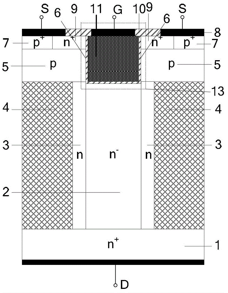
[0032] In this example, an N-channel trench-gate VDMOS device with a low-resistance current channel is taken as an example. The cross-sectional view is as follows figure 2 . In the case of N-channel VDMOS devices the semiconductor substrate is n + Type doping (that is, n-type dielectric with doping concentration greater than n-type doping concentration).

[0033] The slot-gate semiconductor power device in this example includes n + Type-doped semiconductor substrate 1, trench gate structure 13, active region, semiconductor drift region and two high-K dielectric regions 4, the semiconductor drift region includes a first semiconductor region 2 and two second semiconductor regions 3, the first The semiconductor region 2 is arranged above the semiconductor substrate 1, the two second semiconductor regions 3 are arranged above the semiconductor substrate 1, the high-K dielectric region 4 is arranged above the semiconductor substrate 1, and the two sides of the first semiconducto...


PUM


Abstract

The invention relates to semiconductor technologies and provides a groove-gate semiconductor power device which is used for solving the problem that the high-K dielectric role of the existing semiconductor device can not be played under the conditions of relatively-large spacing and small density of dielectric grooves. The technical scheme adopted by the invention can be summarized as follows: two high-K dielectric regions are additionally arranged at the left side and right side of a semiconductor drift region, the two sides of a first semiconductor region in the semiconductor drift region are in contact with two second semiconductor regions, and the two high-K dielectric regions are respectively in contact with the other sides of the two second semiconductor regions. The groove-gate semiconductor power device has the beneficial effects that the specific on-resistance is reduced, the voltage resistance is improved, and the groove-gate semiconductor power device is applicable to an MOS (Metal-Oxide Semiconductor) device or an MOS-controlled semiconductor device.

Description

technical field [0001] The invention relates to semiconductor technology, in particular to a low-power semiconductor power device with a dielectric groove and a groove gate structure. Background technique [0002] The high voltage resistance of power MOSFET (metal oxide semiconductor Field-Effect Transistor) requires a long drift region and low doping concentration in the drift region, which makes the ratio of on-resistance R on,sp Press R according to the device withstand voltage BV on,sp ∝BV 2.3~2.6 The relationship increases, resulting in increased power consumption. [0003] The specific on-resistance drop of the planar gate VDMOS (vertical double diffusion metal oxide semiconductor, vertical double diffusion metal-oxide-semiconductor field effect transistor) has reached its limit due to the limitation of the JFET (junction field-effect transistor) effect. Since the UMOS (U-type trench MOS, U-type trench MOS) structure has no JFET effect and high channel density, its ...

Claims


Application Information

Patent Timeline
Patent Type & Authority Applications(China)
IPC IPC(8): H01L29/06H01L29/78
CPCH01L29/0878H01L29/7813H01L29/7397H01L29/0653H01L29/0634
Inventor 罗小蓉蒋永恒蔡金勇范叶王沛王骁伟周坤王琦罗尹春张波
Owner UNIV OF ELECTRONICS SCI & TECH OF CHINA
Why Eureka
Try Eureka