Flywheel battery supported and driven by split magnetic levitation switch reluctance motor

A technology of switched reluctance motors and flywheel batteries, which is applied in the direction of electric components, magnetic attraction or thrust holding devices, bearings, etc., and can solve the problem of limiting the increase of the critical speed of the flywheel battery and the increase of the energy storage capacity, and the limitation of the flywheel battery Problems such as energy storage density and energy storage efficiency, large volume of flywheel batteries, etc., achieve the effect of reducing volume and cost, firm and reliable structure, and increasing energy storage capacity

Inactive Publication Date: 2012-10-10
JIANGSU UNIV
View PDF7 Cites 19 Cited by
  • Summary
  • Abstract
  • Description
  • Claims
  • Application Information

AI Technical Summary

Problems solved by technology

[0004] Due to the permanent magnets on the rotor of the permanent magnet motor and the windings on the rotor of the asynchronous motor, the motor has a large no-load loss and low reliability under high-speed operation. Therefore, the increase of the critical speed of the flywheel battery and the increase of the energy storage capacity are limited.
In the flywheel battery of the prior art, the flywheel rotor, hybrid magnetic beari

Method used


Image

  • Flywheel battery supported and driven by split magnetic levitation switch reluctance motor
  • Flywheel battery supported and driven by split magnetic levitation switch reluctance motor
  • Flywheel battery supported and driven by split magnetic levitation switch reluctance motor

Examples


Embodiment Construction

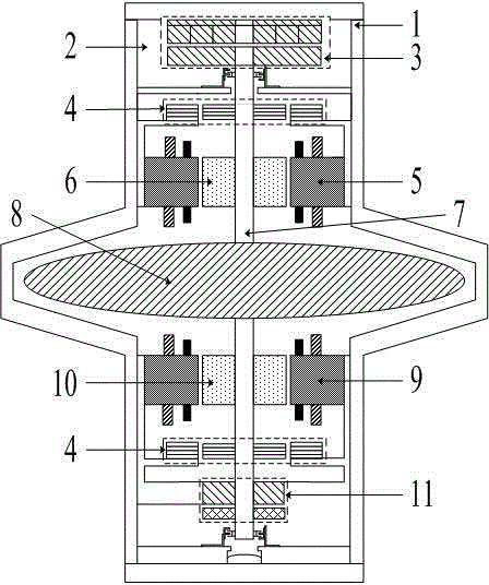
[0017] see figure 1 As shown, the present invention includes a housing 1 and a sealed vacuum chamber 2 surrounded by the housing 1 . In the vacuum chamber 2, the axial permanent magnetic bearing 3, two radial permanent magnetic bearings 4, the split magnetic levitation switched reluctance motor A, the flywheel shaft 7, the flywheel rotor 8, the split magnetic levitation switched reluctance motor B and the shaft To the electromagnetic bearing 11. Wherein, the flywheel rotor 8 is fixedly sleeved on the axially middle position of the flywheel rotating shaft 7 and rotates together with the flywheel rotating shaft 7 . On the flywheel rotating shaft 7 located on the upper part of the flywheel rotor 8, the motor A, the radial permanent magnetic bearing 4 and the axial permanent magnetic bearing 3 are fixedly installed in the axial direction of the flywheel rotating shaft 7 from bottom to bottom. On the flywheel rotating shaft 7 , the motor B, another radial permanent magnetic beari...


PUM


Abstract

The invention discloses a flywheel battery supported and driven by a split magnetic levitation switch reluctance motor. The flywheel battery comprises an enclosure and a vacuum cavity, wherein an axial permanent magnet bearing, two radial permanent magnet bearings, a motor A, a flywheel rotation shaft, a flywheel rotor, a motor B and an axial electromagnetic bearing are contained in the vacuum cavity; the flywheel rotor is fixedly sleeved at the axial center of the flywheel rotation shaft; the axial permanent magnet bearing and the axial electromagnetic bearing are arranged at the upper and lower ends of the flywheel rotation shaft respectively; the two radial permanent magnet bearings are located below the axial permanent magnet bearing and above the axial electromagnetic bearing respectively; the motor A and the motor B are arranged between the two radial permanent magnet bearings and the flywheel rotor respectively; a torque winding of the motor A and a torque winding of the motor B are connected in series, and the levitation windings are independently wound; the axial electromagnetic bearing provides controllable levitation with axial degree of freedom; the levitation winding is excited to generate radial levitation force; and the radial levitation force and the radial restoring force of the radial permanent magnet bearing provide controllable levitation with more than 4 radial degrees of freedom, thereby improving the energy storing efficiency.

Description

technical field [0001] The invention relates to the field of a flywheel battery (also called a flywheel energy storage device), in particular to a flywheel battery supported and driven by a split-type magnetic levitation switched reluctance motor. Background technique [0002] Among many energy storage devices, flywheel batteries break through the limitations of chemical batteries and use physical methods to store energy. When the flywheel rotates at a certain angular velocity, it has a certain kinetic energy, and the flywheel battery converts the kinetic energy into electrical energy. Flywheel batteries are expected to become the most promising energy storage batteries due to their outstanding advantages such as large energy storage, strong power, high efficiency, long life, fast charging and discharging, and clean and pollution-free. [0003] The working principle of the flywheel battery is: there is a motor in the flywheel battery, and the motor operates in the form of a...

Claims


Application Information

Patent Timeline
IPC IPC(8): H02K7/02H02N15/00
CPCY02E60/16F16C32/04F16C2361/55
Inventor 项倩雯孙玉坤嵇小辅张新华
Owner JIANGSU UNIV
Why Eureka
Try Eureka