
Movable narrow crack blade

A blade and slit technology, applied in the field of adjustable lithography machine components, can solve the problems of thermal deformation of the movable blade, interference of the exposure process, and no better method, so as to improve control accuracy, reduce deformation, and improve maintainability Effect

Active Publication Date: 2012-10-17
SHANGHAI MICRO ELECTRONICS EQUIP (GRP) CO LTD
View PDF5 Cites 5 Cited by
  • Summary
  • Abstract
  • Description
  • Claims
  • Application Information

AI Technical Summary

Problems solved by technology

[0003] The following unavoidable problems exist in the movable slit: 1. The movable blade is heated and deformed under exposure for a long time so that it cannot meet its mechanical requirements; 2. The reflected light of the movable blade enters the optical path and interferes with the exposure process.
However, these two problems are also contradictory at the same time. To reduce the thermal deformation of the movable knife edge, it is necessary to increase its reflectivity and reduce its absorption of light energy, but too much reflected light entering the optical path will affect the dose control of exposure. precision
[0004] At present, there is no better way to solve the above problems in the industry.

Method used


Image

  • Movable narrow crack blade
  • Movable narrow crack blade
  • Movable narrow crack blade

Examples


Embodiment Construction

[0027] In order to better understand the technical content of the present invention, specific embodiments are given together with the attached drawings for description as follows.

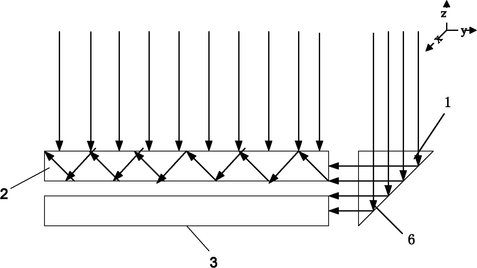
[0028] Please see figure 1 . figure 1 Shown is a schematic structural view of the movable slit blade in the embodiment of the present invention.

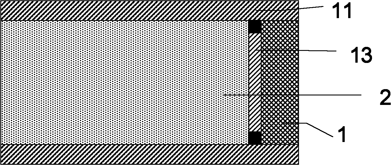
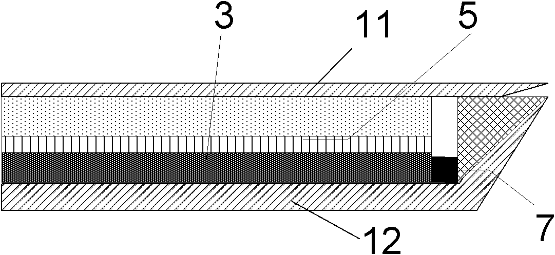
[0029] The structure of a blade 10 of the movable slit is as figure 1 As shown, a light-transmitting plate 2 and a light-absorbing sheet 3 are arranged along the incident light direction. In addition, the blade 10 also includes a reflective prism 1, which is located on the side of the light-transmitting plate 2 and the light-absorbing sheet 3, and there is a gap G between the light-transmitting plate 2 and the light-absorbing sheet 3. .

[0030] The transparent plate 2 is, for example, a quartz plate for transmitting incident light. In order to increase the light transmission capability of the light-transmitting plate 2 , an anti-reflection film may ...


PUM


Abstract

The invention brings forward a movable narrow crack blade, which is used to form an exposure field size of a mask aligner. The movable narrow crack blade comprises a light-passing plate and a light absorption plate along the incident light direction. The light-passing plate is used for conducting incident light and the light absorption plate is used for absorbing incident light. A reflection prism is also arranged at the side of the light-passing plate and the light absorption plate. There is spacing between the reflection prism and the light-passing plate, reflecting the incident light into the light-passing plate and the light absorption plate. The movable narrow crack blade provided by the invention has advantages of position accuracy and adjustable performance, will not influence exposure precision, and has high maintainability.

Description

technical field [0001] The invention relates to an adjustable photolithography machine assembly, and in particular to a movable slit blade. Background technique [0002] In a scanning lithography machine, multiple movable blades form a movable slit, and the lithography machine can use the movable slit to control the position and size of the field of view in the scanning direction. The light is blocked by the movable blade and transmitted through the movable slit. [0003] The movable slit has the following unavoidable problems: 1. The movable blade is heated and deformed under exposure for a long time so that its mechanical requirements cannot be met; 2. The reflected light of the movable blade enters the optical path and interferes with the exposure process. However, these two problems are also contradictory at the same time. To reduce the thermal deformation of the movable knife edge, it is necessary to increase its reflectivity and reduce its absorption of light energy, ...

Claims


Application Information

Patent Timeline
IPC IPC(8): G03F7/20G02B17/08G02B1/10G02B7/18G02B7/00G02B1/00
Inventor 曹昌智
Owner SHANGHAI MICRO ELECTRONICS EQUIP (GRP) CO LTD
Learn More