Metallic target generator without vibrating rod

A metal target and generator technology, which is applied in X-ray tubes with huge currents, microlithography exposure equipment, discharge tubes, etc., can solve the problems of uneven falling track and deviation of metal targets

Inactive Publication Date: 2012-10-17
HUAZHONG UNIV OF SCI & TECH
View PDF5 Cites 8 Cited by
  • Summary
  • Abstract
  • Description
  • Claims
  • Application Information

AI Technical Summary

Problems solved by technology

However, there is a small inherent disturbance in the metal jet in this scheme. This disturbance not only produces uneven metal targets, but also causes deviations in the falling trajectory of the metal targets due to vibrations. The position is very precise, which should be avoided in extreme ultraviolet lithography machines with high precision

Method used


Image

  • Metallic target generator without vibrating rod
  • Metallic target generator without vibrating rod
  • Metallic target generator without vibrating rod

Examples


Embodiment 1

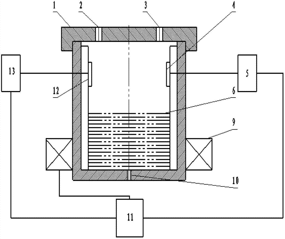
[0057] figure 2 It is a metal target generator without a vibrating rod according to the present embodiment, which includes a cylinder body with an upper cover 1 on the top of the cylinder body, liquid metal 6 is placed in the cylinder body, and a micropore 10 is arranged at the center of the bottom of the cylinder body. The metal liquid drips through the micropores, and an electromagnetic coil 9 is arranged on the outer peripheral wall of the lower part of the cylinder, which generates a changing electromagnetic field by passing in a changing current, and the changing electromagnetic field stirs the liquid metal 6 in the cylinder. , when the liquid metal 6 drops from the micropore 10, it is a metal target that is evenly dropped.

[0058] And the cylinder is also provided with a pressure sensor 12 for detecting the pressure in the cylinder and a temperature sensor 4 for detecting the temperature in the cylinder. The pressure sensor 12 and the temperature sensor 4 are connected...

Embodiment 2

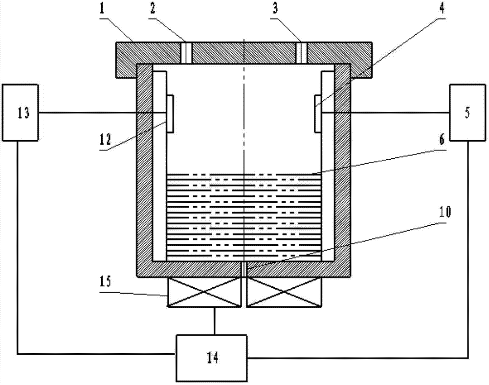
[0072] image 3 It is another kind of electromagnetic stirring current breaking device without a vibrating rod. The difference between this embodiment and Embodiment 1 is that the electromagnetic coil 15 used to generate the driving force for stirring the liquid metal in the cylinder is located at the bottom of the cylinder. When the variable frequency current is input, (similarly) a traveling wave magnetic field will be generated. This magnetic field will pass through the bottom of the container and act on the molten metal, generating induced electric potential and current in the molten liquid. The induced current and the magnetic field will generate electromagnetic Force, so as to promote the directional flow of molten metal and play a stirring role.

[0073] like image 3 As shown, the temperature sensor 4 transmits the measured temperature in the container to the temperature control system 5 to adjust the system temperature. The pressure measured by the pressure sensor 1...

Embodiment 3

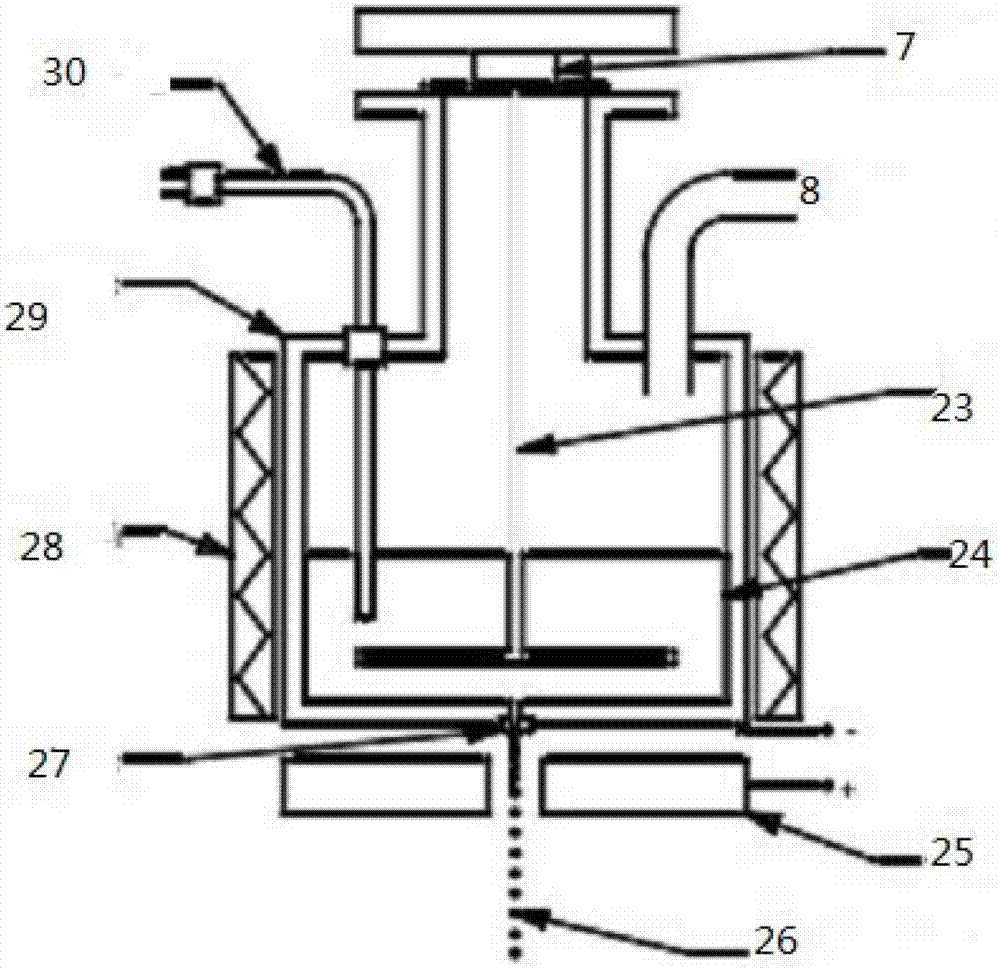
[0075] Image 6 As shown, the micropore 10 in this embodiment protrudes from the bottom of the cylinder and extends outward to form a tubular channel, and the electromagnetic coil 9 is symmetrically arranged on the outer periphery of the protruding hole wall of the micropore channel 10 .

[0076] According to the knowledge of electromagnetism, the molten metal will produce forced flow under the action of the rotating magnetic field, and the flow direction of the flowing metal liquid can be reversed. This device uses this principle to control the frequency of producing metal targets by controlling the closure of the rotating magnetic field. When working, the jet fills the entire micropore, and a rotating magnetic field is applied at the micropore. Since the jet flows downward under pressure control, when the rotating magnetic field is turned on, the jet is subject to a large Lorentz force. This rotational force can make the jet The change of the flow direction has a braking eff...


PUM


Abstract

The invention discloses a metallic target generator without a vibrating rod. The metallic target generator comprises a cylindrical shell which accommodates liquid metal (6) used for generating metallic targets and a micropore (10) which is provided at the bottom of the cylindrical shell and allows the metal liquid to flow out; the metallic target generator is characterized in that the generator further comprises electromagnetic coils (9, 15, 37 and 38) and after the electromagnetic coils are energized, the electromagnetic coils generate electromagnetic forces and exert the electromagnetic forces on the liquid metal (6) so as to allow fluid flowing out from the micropore (10) to form uniformly dropped metallic targets, thereby further allowing a metallic target material to be formed. The metallic target generator provided the invention realizes jet breakup by using an electromagnetic field without using a vibrating rod, which enables fluctuation of liquid metal to be avoided and a small volume and a stable dropping interval of metallic targets to be achieved.

Description

technical field [0001] The invention relates to a metal target generator used in an EUV lithography machine. Background technique [0002] In the next-generation lithography machine technology, the 13.5nm laser plasma EUV light source using a metal target is regarded as the most promising light source. At present, the methods for generating EUV light sources mainly include discharge plasma method (LPP) and Laser plasma method (DPP). Compared with DPP technology, LPP technology has more characteristics required by lithography, such as higher output power and better working stability. An ideal EUV light source based on LPP technology, the main components should include a carbon dioxide laser, a micro-metal target generator, a debris elimination device, a light concentrating and a spectral purification device, the main principle of which is that the laser passes through the mirror and irradiates the metal On the target, bombardment of the metal target produces plasma, which p...

Claims


Application Information

Patent Timeline
Patent Type & Authority Applications(China)
IPC IPC(8): G03F7/20H05G2/00
Inventor 李小平苗怀坤陈学东
Owner HUAZHONG UNIV OF SCI & TECH
Why Eureka
Try Eureka