Parameter identification control device and control method of sensorless permanent magnet synchronous motor

A permanent magnet synchronous motor, parameter identification technology, applied in the direction of motor generator control, electromechanical transmission control, electronic commutation motor control, etc., can solve the problem of parameter identification

A permanent magnet synchronous motor, parameter identification technology, applied in the direction of motor generator control, electromechanical transmission control, electronic commutation motor control, etc., can solve the problem of parameter identification

CN102739150AInactive Publication Date: 2012-10-17HARBIN INST OF TECH

Image

  • Parameter identification control device and control method of sensorless permanent magnet synchronous motor
  • Parameter identification control device and control method of sensorless permanent magnet synchronous motor
  • Parameter identification control device and control method of sensorless permanent magnet synchronous motor

Examples


specific Embodiment approach 1

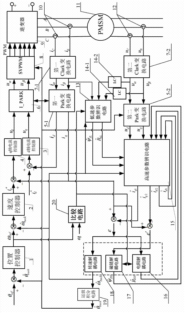
[0042] Specific implementation mode one: the following combination figure 1 Describe this embodiment, the parameter identification control device of sensorless permanent magnet synchronous motor described in this embodiment, it includes permanent magnet synchronous motor 11, it also includes position sensor 1, speed controller 2, d-axis current controller 3, q Shaft current controller 4, first Park transformation circuit 5-1, second Park transformation circuit 5-2, inverse Park transformation circuit 6, first Clark transformation circuit 7-1, second Clark transformation circuit 7-2, space vector Pulse width modulation circuit 8, inverter 9, current transformer 10, voltage sensor 12, low-speed parameter identification circuit 13, first LC filter circuit 14-1, second LC filter circuit 14-2, high-speed parameter identification circuit 15, Resistance decoupling circuit 16, flux linkage decoupling circuit 17, speed decoupling circuit 18, operational amplifier integration circuit 19...

specific Embodiment approach 2

[0048] Specific implementation mode two: the following combination figure 1 This embodiment is described. This embodiment is a parameter identification control method for a sensorless permanent magnet synchronous motor based on the parameter identification control device for a sensorless permanent magnet synchronous motor described in Embodiment 1.

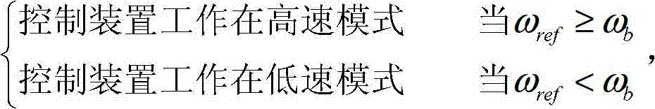
[0049] Comparator circuit 20 takes motor rotor speed given signal value ω ref Compared with the motor rotor speed ω bAfter the comparison, the operating mode of the control device is controlled by the comparison result, specifically:

[0050]

[0051] when ω ref b , the low-speed parameter identification circuit 13 is enabled under the control of the selection control signal output by the comparison circuit 20, and the flux linkage decoupling circuit 17 and the resistance decoupling circuit 16 stop running. At this time, the β output from the first LC filter circuit 14-1 The axis filtered voltage signal and the α-axis filter...

specific Embodiment approach 3

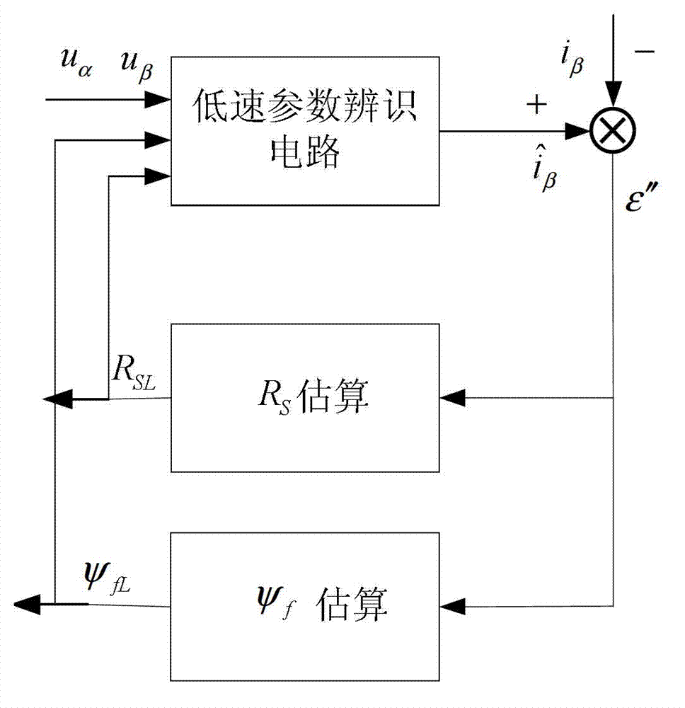
[0054] Specific implementation mode three: the following combination figure 2 Describe this embodiment, this embodiment is a further description of Embodiment 2, the d-axis current component and q-axis current It is obtained by solving the following formula:

[0055] d dt i ^ d 1 i ^ q 1 = - R s L s ...


PUM


Abstract

The invention discloses a parameter identification control device and a parameter identification control method of a sensorless permanent magnet synchronous motor, belongs to the technical field of control over the sensorless permanent magnet synchronous motor, and solves the problem that parameters cannot be identified by the conventional permanent magnet synchronous motor positionless control method when a motor operates in a rotating speed range. Parameter identification of the sensorless permanent magnet synchronous motor in each speed stage is realized by improvement of a control policy and a control method. In medium-high-speed stages, input amount is modeled by constructing a circuit, and output parameters are obtained; and in low-speed and zero-speed stages, the accuracy of model output amount is realized according to the accuracy of model input parameters. By the invention, a three-closed-loop control mode is employed, and the working modes of a system are switched according to the size of rotating speed in the parameter identification process. The invention is applicable to parameter identification of the sensorless permanent magnet synchronous motor.

Description

technical field [0001] The invention relates to a parameter identification control device and a control method of a sensorless permanent magnet synchronous motor, belonging to the technical field of sensorless permanent magnet synchronous motor control. Background technique [0002] With its high power density, high efficiency, wide speed range, and fast response, permanent magnet synchronous motors are widely used in high-precision transmission fields such as CNC machine tools, industrial robots, and aerospace equipment, as well as energy-saving fields such as household appliances, fans, and pumps. . In order to detect the speed and position of the permanent magnet synchronous motor, it is necessary to add sensors to the motor. At present, the mechanical position sensors commonly used in permanent magnet synchronous motors include photoelectric encoders, resolvers, Hall and inductive synchronizers. While these mechanical position sensors can provide rotor magnetic pole pos...

Claims


Application Information

Patent Timeline
17 Oct 2012
Publication
CN102739150A
IPC
H02P21/14; H02P21/13; H02P21/18
Inventors
刘剑; 李彦